
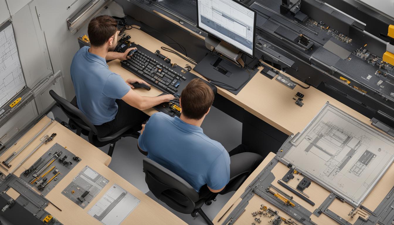
Computer Numerical Control (CNC) machines fundamentally rely on programming to execute precise manufacturing tasks. These sophisticated systems translate digital instructions into physical movements, enabling the automated production of complex components. Without a defined program, a CNC machine remains an inert collection of hardware, incapable of performing any machining operation.
Modern manufacturing environments demand high accuracy and repeatability, which CNC programming delivers by eliminating much of the variability associated with manual intervention. This technological evolution has significantly enhanced production speed and reliability across various industries.
G-Code: the Core Language of CNC
G-code, often referred to as ‘Geometric Code,’ serves as the primary programming language for CNC machines. It dictates the geometric path of the cutting tool, instructing the machine on where to move, how fast to go, and along which axis. Each line of a G-code program, known as a block, contains a set of commands that precisely control the machine’s actions.
Beyond geometric movements, M-codes, or ‘Miscellaneous Codes,’ manage non-motion machine functions. These include critical operations such as turning the spindle on and off (M03, M05), activating or deactivating coolant (M08, M09), and initiating tool changes (M06). The interplay between G-codes and M-codes allows for comprehensive control over the entire machining process.
Common G-code commands are essential for defining toolpaths and machine behavior. For instance, ‘G00’ commands a rapid, non-cutting movement between points, while ‘G01’ specifies a linear cutting motion at a defined feed rate. Circular interpolation is achieved with ‘G02’ for clockwise arcs and ‘G03’ for counter-clockwise arcs.
Coordinate systems are also fundamental to G-code. ‘G90’ establishes absolute positioning, where all movements are referenced from a fixed origin point. Conversely, ‘G91’ enables incremental positioning, with each movement defined relative to the tool’s current location. These commands ensure the tool navigates the workpiece accurately.
CAD/CAM: Bridging Design to Machine Code
| G-Code | Function | Description |
|---|---|---|
| G00 | Rapid Positioning | Moves the tool quickly between points without cutting. |
| G01 | Linear Interpolation | Moves the tool in a straight line at a specified feed rate while cutting. |
| G02 | Circular Interpolation CW | Executes a clockwise circular arc movement. |
| G03 | Circular Interpolation CCW | Executes a counter-clockwise circular arc movement. |
| G90 | Absolute Positioning | All coordinates are referenced from the program origin. |
| G91 | Incremental Positioning | Coordinates are relative to the current tool position. |
| G20 / G21 | Unit Selection | Selects inch (G20) or metric (G21) units for programming. |
The modern CNC programming workflow typically begins with Computer-Aided Design (CAD) software. Engineers create detailed 2D or 3D models that define the part’s geometry, including critical requirements like tolerances and surface finish. This CAD model serves as the ‘geometric truth’ for the manufacturing process.
Following the design phase, Computer-Aided Manufacturing (CAM) software takes over. CAM tools translate the CAD model into machine-readable instructions, generating optimized toolpaths for efficiency and tool life. This process involves defining machining operations, selecting appropriate cutting tools, and setting parameters such as feed rates and spindle speeds.
Post-processing is a crucial step where the generic toolpath data from CAM is converted into specific G-code tailored for a particular CNC machine controller. Each controller, such as Fanuc, Siemens, or Haas, has its own dialect of G-code, requiring a customized post-processor. This ensures the generated code is correctly interpreted and executed by the target machine.
Utilizing CAD/CAM software offers significant advantages, especially for complex geometries and multi-axis machining. It automates the generation of intricate toolpaths, reduces the potential for human error compared to manual coding, and allows for simulation to identify potential issues before actual production begins. This integration streamlines the manufacturing process, enhancing precision and optimizing production workflows.
Conversational Programming and Manual Data Input
Conversational programming provides a user-friendly alternative to traditional G-code for simpler machining tasks, often directly on the shop floor. This method typically employs a menu-driven interface where operators respond to prompts about part geometry, material, and tooling. Controllers from manufacturers like Hurco and Okuma are well-known for their robust conversational capabilities.
Operators can define features such as pockets, bolt circles, or bosses by inputting parameters into a form-based system. The control then automatically generates the necessary G-code in the background. This approach significantly lowers the barrier to entry for machinists transitioning from manual machines, as it aligns with their existing operational knowledge.
Manual Data Input (MDI) mode allows operators to enter and execute individual G-code blocks or short sequences of commands directly through the machine’s control panel. MDI is primarily used for immediate, temporary operations that do not require a full program.
Common applications for MDI include manual machine setup, such as executing tool changes (‘M06’), starting or stopping the spindle (‘M03’, ‘M05’), controlling coolant (‘M08’, ‘M09’), or performing rapid axis movements for referencing. It is also invaluable for troubleshooting, testing specific program sections, or performing quick, simple operations without the need to write or load an entire program.
Loading and Executing CNC Programs
Once a CNC program is generated, it must be loaded into the machine’s controller. Several methods facilitate this transfer, with USB drives being a common and convenient option. Operators insert the USB drive into the machine’s port and navigate the control interface to load or copy the program to the machine’s internal memory.
In industrial settings, connecting via Ethernet or a network is often preferred for its efficiency. If the CNC machine is networked, programs can be transferred directly from a shared computer folder. Older machines may utilize an RS-232 serial port, requiring a cable connection to a computer running Direct Numerical Control (DNC) software and careful configuration of communication parameters.
Before executing a program, thorough machine preparation is essential. This includes a warm-up period to circulate lubricants and ensure thermal stability, as well as securely installing workpieces with appropriate clamps, vises, or fixtures. Safety checks are also critical to ensure all limits are in place and prevent accidents during machining.
Program verification is a modern engineering practice that significantly reduces risks. Utilizing simulation software to preview machine operations helps identify potential issues like tool collisions or incorrect toolpaths before any material is cut. After verification, the program can be executed, often starting with a ‘dry run’ or ‘air cut’ to confirm the machine follows the intended path safely without engaging the tool.