
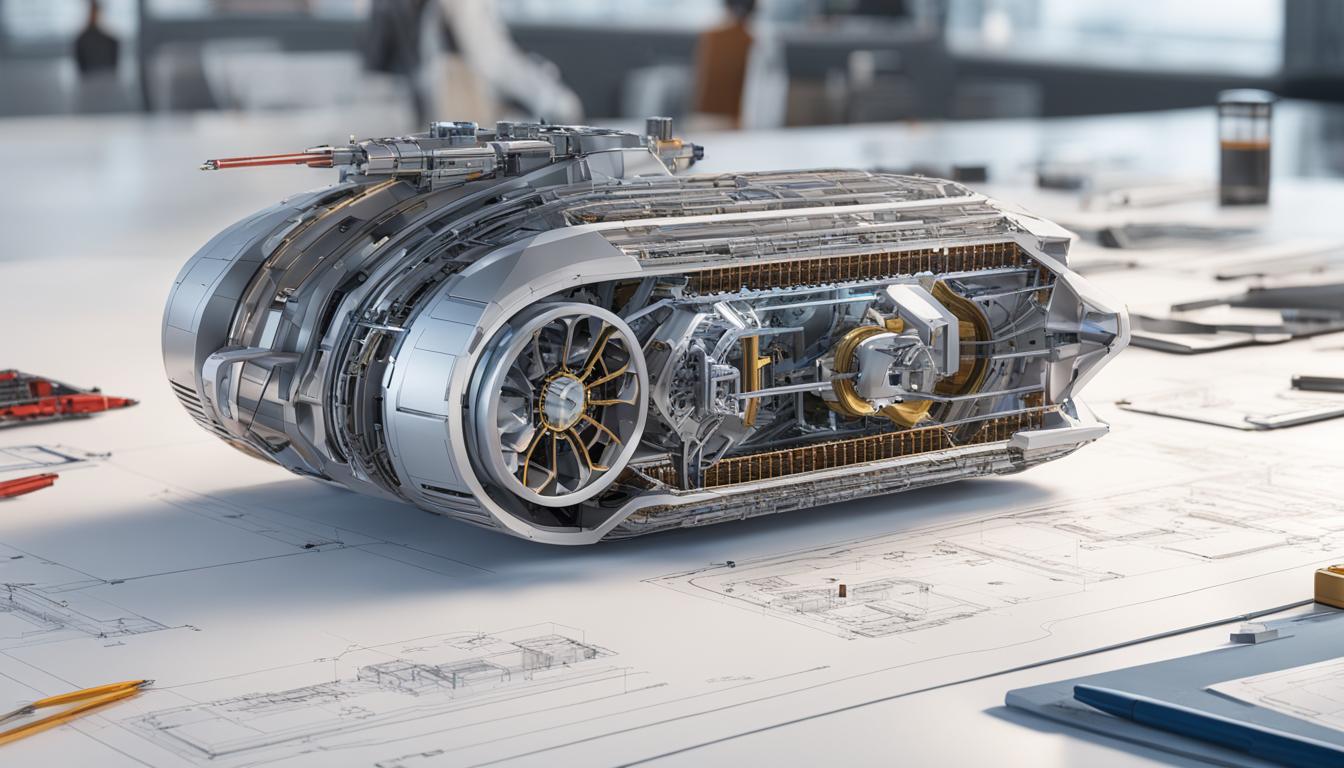
SolidWorks remains a cornerstone in modern engineering, providing a robust platform for 3D CAD modeling, simulation, and manufacturing preparation. Its integrated environment streamlines the product development lifecycle, from initial concept to final production. Engineers leverage its comprehensive toolset to create intricate designs, analyze performance, and generate precise manufacturing data.
This guide delves into key technical aspects of SolidWorks, offering a detailed exploration of its capabilities. Understanding these functionalities is crucial for any tooling engineer aiming to optimize design workflows and ensure manufacturing accuracy.
Parameter-Driven 3D CAD Modeling
Parameter-driven modeling forms the foundation of efficient design in SolidWorks, allowing engineers to define ‘design intent’—how a model should behave when modified. This approach ensures that changes propagate predictably throughout the design, maintaining geometric relationships and functional requirements. Sketch relations, for instance, are geometric constraints that define the size, shape, location, and orientation of sketch entities, crucial for implementing design intent.
Features are built upon fully defined sketches, incorporating dimensions and relations that control their behavior. Common parametric features include extrudes, revolves, sweeps, and lofts, each offering distinct methods for creating 3D geometry. Modifying a dimension or relation automatically updates the associated features, saving significant time in iterative design processes.
Configurations provide a powerful method for managing multiple variations of a single part or assembly within one file. These can represent different sizes, material options, or suppressed features. Design tables, often utilizing embedded Excel spreadsheets, enable rapid creation and modification of numerous configurations by controlling various parameters, dimensions, and suppression states. This capability is invaluable for product families or standard components.
SolidWorks CAM Toolpaths
| Nominal Length Range (mm) | Tolerance (±mm) |
|---|---|
| 0.5 up to 3 | 0.1 |
| Over 3 up to 6 | 0.1 |
| Over 6 up to 30 | 0.2 |
| Over 30 up to 120 | 0.3 |
| Over 120 up to 400 | 0.5 |
| Over 400 up to 1000 | 0.8 |
| Over 1000 up to 2000 | 1.2 |
| Over 2000 up to 4000 | 1.6 |
SolidWorks CAM integrates computer-aided manufacturing directly within the CAD environment, converting 3D models into CNC machining operations and toolpaths. This seamless integration eliminates data translation issues and accelerates programming time, as design changes automatically update associated manufacturing information. The system supports 2.5-axis and 3-axis milling, along with turning operations.
Various toolpath strategies are available for different machining requirements, including roughing, finishing, contouring, and pocketing. Automatic Feature Recognition (AFR) identifies machinable features on the model, simplifying the setup process. Tool libraries allow for standardized tool selection, while post-processors generate machine-specific G-code.
Simulation capabilities within SolidWorks CAM are critical for verifying toolpaths before physical machining. This allows engineers to detect potential collisions, excessive material removal, or tool interference, ensuring optimal and safe machining processes. For example, when machining 6061 aluminum with a 1/2 inch, 3-flute carbide end mill, typical parameters might include a surface speed of 800-1200 SFM and a chip load of 0.003-0.005 inches per tooth, adjusted based on depth of cut and machine rigidity.
Assembly Design Constraints
Assembling components in SolidWorks relies heavily on ‘mates,’ which define the geometric relationships and degrees of freedom between parts. Standard mates like coincident, concentric, parallel, and perpendicular are fundamental for positioning components accurately. Distance and angle mates provide precise control over component separation and orientation.
Advanced mates offer more sophisticated control over assembly behavior. These include width mates for centering components, path mates for constraining movement along a defined curve, and limit mates to restrict linear or angular motion within a specified range. Symmetric mates ensure components remain mirrored across a plane, while linear/linear coupler mates link the movement of two components.
The Mate Controller is a powerful tool for programming and controlling the positions of assembly components without creating numerous configurations. It allows users to define and recall multiple positions, facilitating the creation of complex mechanisms and animations for design reviews and presentations. This feature is particularly useful for analyzing kinematic motion.
Engineering Drawing Creation
Engineering drawings serve as the universal language for manufacturing, conveying all necessary information for part production and inspection. SolidWorks facilitates the creation of detailed drawings with various standard views, including orthographic (front, top, right), isometric, section, and detail views. These views are essential for fully communicating design intent.
Dimensioning and tolerancing are critical elements of any engineering drawing. SolidWorks supports comprehensive Geometric Dimensioning and Tolerancing (GD&T) in accordance with standards like ASME Y14.5. GD&T symbols define precise form, orientation, location, and runout tolerances, ensuring interchangeability and proper function of manufactured parts.
General tolerances, such as those defined by ISO 2768-mK, are applied to dimensions without explicit individual tolerances. This standard specifies permissible deviations for linear, angular, and geometrical features, streamlining drawings by reducing the need for individual tolerance callouts on every dimension. The ‘mK’ designation signifies medium dimensional tolerances (ISO 2768-1) and K-class geometrical tolerances (ISO 2768-2), commonly used for general machined parts.
Finite Element Analysis (FEA)
SolidWorks Simulation provides integrated Finite Element Analysis (FEA) tools, allowing engineers to test designs virtually within the familiar CAD interface. This capability helps predict product performance under various loading conditions, reducing the need for costly physical prototypes. The typical FEA workflow involves pre-processing, solving, and post-processing.
Pre-processing includes defining material properties, applying fixtures (constraints), and specifying external loads (forces, pressures, temperatures). Meshing, the process of dividing the model into small elements, is a critical step; finer meshes generally yield more accurate results but require greater computational resources. SolidWorks offers automated meshing tools and controls for refining specific areas of interest.
SolidWorks Simulation supports various study types, including linear static analysis to evaluate stress, displacement, and factor of safety under steady loads. Frequency analysis identifies natural vibration characteristics, while buckling analysis assesses stability under compressive loads. More advanced versions offer nonlinear analysis for complex material behaviors, large deformations, and contact conditions. Post-processing involves interpreting results such as stress and strain distributions, displacement plots, and factor of safety maps to identify critical areas and potential failure zones.