
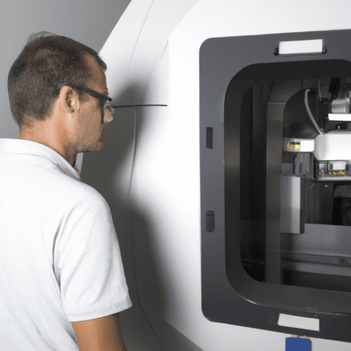
Operating Computer Numerical Control (CNC) machinery involves a complex interplay of technical expertise, meticulous planning, and constant vigilance. The inherent demands of precision manufacturing, coupled with the dynamic nature of production environments, often create a high-pressure atmosphere for tooling engineers and machinists alike.
Achieving consistent, high-quality output requires a deep understanding of material science, cutting tool mechanics, and machine capabilities. Every decision, from programming toolpaths to selecting workholding strategies, directly impacts the final product’s integrity and the overall efficiency of the operation.
Precision Demands and Tolerance Realities
High-value parts, particularly those for aerospace and medical device industries, necessitate extremely tight tolerances. While standard CNC machining typically holds tolerances around ±0.005 inches (±0.127 mm), critical applications often demand precision of ±0.001 inches (±0.0254 mm) or even tighter, reaching 1-5 microns (±0.0001 inches) with specialized techniques.
These stringent requirements mean that even microscopic deviations can lead to part failure, especially in components where dimensional accuracy directly impacts safety and clinical outcomes. Geometric Dimensioning and Tolerancing (GD&T) standards, such as ISO 2768, provide a framework for defining acceptable variations, categorizing tolerances into classes like ‘fine’ (f), ‘medium’ (m), ‘coarse’ (c), and ‘very coarse’ (v) for linear and angular dimensions.
The ‘medium’ (m) tolerance class is widely considered the industry standard for most CNC machined parts, balancing precision with manufacturing cost. However, ‘fine’ (f) tolerances are reserved for critical mating parts, bearing housings, and sealing surfaces, requiring enhanced tool control, slower feed rates, and rigorous inspection processes, which inherently increase production costs.
Surface finish requirements also contribute to the complexity. Achieving specific roughness average (Ra) values often dictates tool selection, cutting parameters, and the number of finishing passes. The interplay between dimensional accuracy and surface quality is a constant consideration for tooling engineers.
Navigating Production Pressures
| Parameter | Standard Tolerance | Precision Tolerance | High-Precision Tolerance |
|---|---|---|---|
| Linear Dimensions (ISO 2768-1) | ±0.1 mm (Medium ‘m’) | ±0.05 mm (Fine ‘f’) | ±0.0025 mm (±0.0001″) |
| Surface Roughness (Ra) | 3.2 – 6.3 µm | 0.8 – 1.6 µm | < 0.4 µm |
| Typical Material | Aluminum 6061, Mild Steel | Stainless Steel 304, Titanium | Medical Grade Titanium, PEEK |
Tight production deadlines are a perpetual source of stress in CNC machining environments. Manufacturers face constant pressure to minimize lead times and maximize machine utilization to meet customer demands and maintain profitability. This often involves optimizing every stage of the production cycle, from programming to post-processing.
Efficient scheduling and workflow management are critical to prevent bottlenecks and ensure a steady flow of parts. The need for rapid prototyping and scalable production, particularly in sectors like medical devices, compresses development cycles significantly, sometimes from several weeks to just a few.
Balancing speed with precision is a delicate act. Aggressive feeds and speeds can reduce cycle times but may compromise surface finish, accelerate tool wear, or even lead to tool breakage. Conversely, overly conservative parameters extend production times, impacting delivery schedules and overall output.
Tooling engineers must continuously evaluate and adjust cutting parameters based on material properties, tool geometry, and machine rigidity. For instance, milling aluminum often requires spindle speeds between 8,000-12,000 RPM with feed rates of 40-80 IPM, while turning 304 stainless steel with coated carbide might use cutting speeds of 150-220 m/min and roughing feed rates of 0.20-0.40 mm/rev.
Mitigating Machine Crash Hazards
Machine crashes represent a significant risk in CNC operations, leading to costly downtime, damaged equipment, scrapped parts, and potential injury. These incidents can stem from various factors, including programming errors, incorrect tool offsets, improper workholding, or operator mistakes.
Incorrect tool length measurements or mismatched work coordinate systems (WCS) are common culprits, causing the tool to engage the workpiece or fixture at an unintended position. Tool wear that is not properly compensated can also lead to gradual dimensional drift, eventually resulting in a crash or out-of-tolerance parts.
Preventative measures are paramount. Implementing robust simulation software, conducting thorough program verification, and utilizing automated tool setters and probing systems can significantly reduce crash risks. Regular machine calibration and maintenance also help mitigate issues like thermal expansion and mechanical backlash that can affect accuracy over time.
Workholding stability is another critical factor. Poorly secured workpieces can vibrate, chatter, or even shift under cutting forces, leading to inaccurate cuts, poor surface finishes, and potential tool or machine damage. Precision-engineered chucks, collets, and custom fixtures are essential for maintaining rigidity and preventing movement during machining.
Mastering Setup and Troubleshooting
The setup phase of any CNC job is inherently complex and prone to errors, demanding meticulous attention to detail. Proper tool offset management is fundamental; these values compensate for tool wear, measurement inaccuracies, and other factors that influence a part’s final dimensions.
Operators must accurately measure tool lengths and diameters, then input these values into the machine’s control. Errors in this process, such as incorrect manual entries or misapplication of G43/G49 commands for tool length compensation, can lead to significant dimensional inaccuracies and scrapped parts.
Troubleshooting often involves diagnosing issues like chatter marks, poor surface finishes, or out-of-tolerance dimensions. These problems can arise from a multitude of sources, including improper feeds and speeds, worn tools, loose workholding, or machine rigidity issues.
Effective troubleshooting requires a systematic approach, starting with verifying tool and work offsets, inspecting cutting tools for wear, and ensuring workpiece stability. Adjusting cutting parameters, minimizing tool overhang, and checking machine components for looseness are common corrective actions.
Optimizing Shop Floor Environment
Workplace shop conditions significantly impact operator well-being, productivity, and the overall quality of machining operations. Ergonomics plays a crucial role, focusing on designing workstations, tools, and processes to fit the worker, thereby reducing fatigue and the risk of musculoskeletal disorders (MSDs).
Factors such as adjustable workstation heights, easily accessible control panels, and proper lighting contribute to operator comfort and efficiency. Reduced reach to the spindle and shorter door-to-table distances also improve setup times and reduce physical strain.
Exposure to coolant mist poses significant health risks, including respiratory problems like asthma, bronchitis, and even lung disease, as well as skin conditions such as dermatitis. Implementing local exhaust ventilation (LEV) systems, ensuring proper machine enclosures, and providing appropriate personal protective equipment (PPE) are essential for mitigating these hazards.
Noise levels in CNC shops can also contribute to stress and hearing damage over time. While specific regulations vary, maintaining a quieter environment through machine enclosures, sound-dampening materials, and hearing protection is vital for long-term operator health and focus. A well-maintained and ergonomically designed shop floor fosters a more productive and less stressful environment for precision manufacturing.