
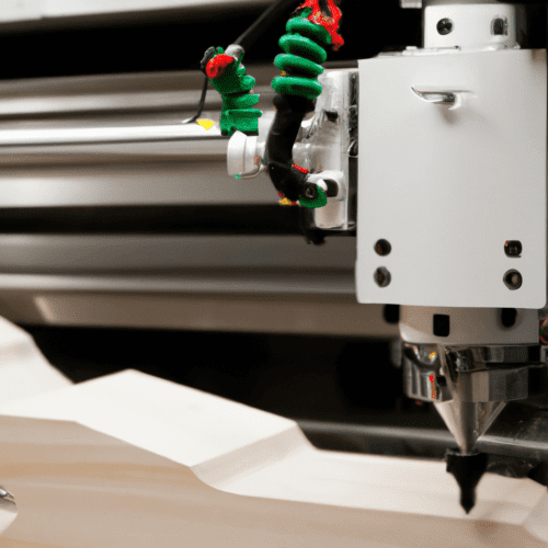
CNC mills are highly capable machines for processing wood, offering precision and repeatability far exceeding manual methods. While often associated with metalworking, these versatile tools, particularly CNC routers, excel at transforming various wood types into intricate designs and functional components. Understanding the specific parameters for wood machining is crucial for optimal results and tool longevity.
Optimizing Spindle Performance for Wood
CNC router spindles operate at significantly higher RPMs compared to traditional metalworking VMCs. Typical operating ranges for wood applications span from 8,000 to 24,000 RPM, with some trim routers reaching up to 30,000 RPM. This elevated speed is essential because router bits generally feature fewer flutes, often one to three, and wood’s softer nature allows for higher surface speeds without causing excessive tool wear.
Maintaining the correct spindle speed is critical for achieving a clean cut and preventing material damage. Running too high an RPM without a proportional increase in feed rate can lead to the bit rubbing the material instead of cutting, generating excessive heat, causing burn marks, and rapidly dulling the tool. Conversely, a spindle with insufficient wattage may lose RPM under load, especially in dense hardwoods, leading to chatter and poor surface finish. Higher wattage spindles, such as 1000W air-cooled units, can sustain set RPMs, enabling faster feed rates and consistent chip load.
Effective Chip Evacuation and Dust Management
| Bit Diameter | Material | Target Chip Load (IPT) | Typical RPM | Typical Feed Rate (IPM) |
|---|---|---|---|---|
| 1/8″ (3.175mm) | Softwood | 0.002–0.004″ | 18,000–22,000 | 50–100 |
| 1/4″ (6.35mm) | Softwood | 0.005–0.008″ | 18,000–22,000 | 100–150 |
| 1/4″ (6.35mm) | Hardwood | 0.003–0.004″ | 16,000–18,000 | 80–120 |
| 1/4″ (6.35mm) | Plywood | 0.003–0.004″ | 16,000–18,000 | 100–140 |
| 3/8″ (9.525mm) | Softwood | 0.005–0.010″ | 16,000–20,000 | 160–200 |
| 1/2″ (12.7mm) | Softwood | 0.007–0.015″ | 12,000–16,000 | 180–240 |
Efficient dust collection is paramount in CNC woodworking, not only for maintaining a clean workspace but also for ensuring cut quality and operator safety. Wood dust is a combustible material and a respiratory hazard, necessitating robust collection systems. Effective chip evacuation prevents chips from being re-cut, which can lead to increased heat, premature tool wear, and poor surface finish.
CNC routers typically require a dust collection system capable of delivering 400 to 650 CFM at the machine’s dust port, with some sources recommending 550-650 CFM for CNC routers specifically. Industrial setups or those with multiple simultaneously operating machines may require significantly higher CFM, often exceeding 1,000 CFM. Crucially, the system must maintain a minimum air velocity of 4,000 FPM (feet per minute) in the ductwork to prevent wood chips and dust from settling and clogging the lines.
Strategic Bit Selection for Superior Wood Finishes
Selecting the appropriate router bit is fundamental to achieving desired surface finishes and efficient material removal in wood. Upcut, downcut, and compression spiral bits each offer distinct advantages depending on the application. Upcut bits excel at chip evacuation, pulling chips upwards and out of the cut, which is beneficial for deeper cuts and achieving a clean bottom edge. However, they can cause fraying or chip-out on the top surface.
Downcut bits, conversely, push chips downwards, resulting in a very clean top edge with minimal fraying, making them ideal for non-through pockets or materials prone to splintering like veneers and laminates. The downside is that chip compaction can lead to heat buildup and reduced tool life in deeper cuts if feed rates are not adjusted. Compression bits combine both upcut and downcut geometries, providing a clean finish on both the top and bottom surfaces, particularly effective for single-pass through cuts in sheet goods.
Precision Chip Load Settings for Wood
Chip load, defined as the thickness of material removed by each cutting edge per revolution, is the most critical parameter for optimizing CNC wood routing. An incorrect chip load leads to either burning and rubbing (too low) or chipping and tool breakage (too high). The formula for calculating feed rate based on chip load is: Feed Rate (IPM) = Chip Load (inches) × RPM × Number of Flutes.
General chip load ranges vary by bit diameter and wood type. For a 1/4″ diameter bit, a chip load of 0.005 to 0.008 inches per tooth is typical for softwood, while hardwood generally requires 0.003 to 0.004 IPT. When cutting deeper than one tool diameter, it is advisable to reduce the chip load; for instance, a 25% reduction for a depth of two times the diameter and a 50% reduction for three times the diameter.
*Note: These are starting guidelines; always refer to tool manufacturer specifications and adjust based on cut performance.*
Secure Workholding with Vacuum Systems
Vacuum workholding systems offer a highly efficient and precise method for securing wood on a CNC mill, eliminating the need for traditional clamps that can obstruct toolpaths and leave marks. These systems utilize negative air pressure to create a strong suction force, holding the workpiece firmly against the table surface. This method ensures stability, minimizes part movement, and enhances dimensional precision, which is crucial for intricate cuts.
A typical vacuum workholding setup includes a vacuum pump or Venturi generator, a sealed chamber or plenum beneath the part, and a gasket or sealing cord to isolate the work zone. The holding surface often features a grid design with multiple vacuum ports, allowing for flexible configuration to accommodate various workpiece shapes and sizes. Systems like the AirWeights offer significant holding power, with some capable of over 8,000 lbs of force, ensuring secure material retention even during aggressive machining operations.
Standard tolerances for CNC wood machining are generally less stringent than for metals, but precision is still achievable. Typical linear dimensional tolerances for general CNC machining are around ±0.125 mm (±0.005 in), with precision work reaching ±0.025 mm (±0.001 in) or tighter for critical features. Achieving these tighter tolerances in wood requires careful control of feeds, speeds, and tool selection to minimize material deflection and tear-out.