
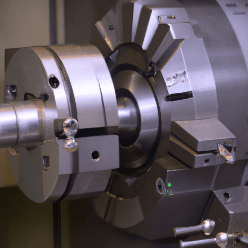
The lathe, a foundational machine tool in manufacturing, offers unparalleled versatility for shaping cylindrical workpieces. Its core principle involves rotating a workpiece against a stationary, single-point cutting tool, enabling a wide array of operations from basic material reduction to intricate feature generation.
Modern CNC lathes, in particular, provide high precision and automation, making them indispensable in industries such as automotive, aerospace, and medical device manufacturing for producing components like shafts, bushings, and threaded parts.
Cylindrical Turning
Cylindrical turning is the most fundamental lathe operation, involving the removal of material from the external diameter of a rotating workpiece to achieve a desired cylindrical shape. This process can be categorized into roughing and finishing passes.
Roughing aims to remove a significant volume of material quickly, often leaving a coarser surface finish and larger tolerances, typically IT11–IT10. Finishing operations, conversely, focus on achieving precise dimensions and superior surface quality, commonly reaching IT7–IT6 tolerances and surface roughness values of 1.6–0.8 µm Ra.
Tooling for cylindrical turning primarily consists of single-point cutting tools, which can be made from High-Speed Steel (HSS) or carbide. Carbide inserts are prevalent in modern CNC machining due to their ability to withstand higher cutting speeds and temperatures, offering increased productivity and tool life.
HSS tools remain valuable for manual lathes, less rigid setups, or when machining tougher materials at lower speeds. Tool geometry, including nose radius, rake angle, and relief angle, significantly influences chip formation, surface finish, and tool durability.
A larger nose radius generally improves surface finish but can increase cutting forces, while positive rake angles reduce cutting forces and are suitable for softer materials.
Optimal speeds and feeds are critical for efficient and high-quality cylindrical turning. For carbide tooling on aluminum alloys like 6061, starting surface speeds of 600 to 1200 surface feet per minute (SFM) are commonly recommended, with roughing feed rates between 0.004 to 0.010 inches per revolution (IPR) and finishing feeds from 0.002 to 0.005 IPR.
When turning steel with HSS tools, recommended cutting speeds are considerably lower, often between 60-100 SFM for alloy steel and around 90 SFM for mild steel. These parameters must be adjusted based on material hardness, tool rigidity, machine capabilities, and desired surface finish to prevent issues like chatter or premature tool wear.
Facing Ends
| Operation | Typical Tolerance (IT Grade) | Typical Surface Finish (Ra) | Common Tooling Material | Typical Carbide SFM (Steel) | Typical Carbide SFM (Aluminum) |
|---|---|---|---|---|---|
| Cylindrical Turning (Fine) | IT7–IT6 | 0.8–1.6 µm (32–63 µin) | Carbide, HSS | 150-300 SFM | 600-1200 SFM |
| Facing (Fine) | IT7–IT6 (integrated with turning) | 0.8–1.6 µm (32–63 µin) | Carbide, HSS | 150-300 SFM | 600-1200 SFM |
| Internal Boring (Precision) | ±0.005–0.01 mm (IT8–IT6) | 0.8–1.6 µm (32–64 µin) | Carbide, Solid Carbide | ~500 SFM (150 m/min) | ~3300 SFM (1000 m/min) |
| Thread Cutting | ASME B1.1 Class 2A/2B or 3A/3B | Dependent on pitch and class | Carbide Inserts, HSS | Varies by material/pitch | Varies by material/pitch |
| Knurling | N/A (dimensional increase) | Textured pattern (not Ra) | Hardened Steel/Carbide Wheels | N/A (forming process) | N/A (forming process) |
Facing is a lathe operation that creates a flat, perpendicular surface on the end of a workpiece, effectively controlling its length and providing a critical reference plane for subsequent machining operations.
This process involves feeding a cutting tool radially across the end face of the rotating part. Achieving a truly flat and square face is paramount, as any deviation can propagate errors throughout the manufacturing process.
Tooling for facing operations typically includes right-hand turning tools with specific insert geometries designed for efficient radial cutting. Carbide inserts are commonly used for their wear resistance and ability to maintain a sharp edge, which is crucial for achieving a smooth surface finish.
The tool’s cutting edge should be positioned precisely on the centerline of the workpiece to prevent a ‘pip’ or ‘nub’ from being left at the center. Modern CNC facing tools often incorporate multiple cutting edges to enhance material removal efficiency, particularly for larger face cuts.
Maintaining tight tolerances and a good surface finish during facing is essential. Typical surface roughness values for fine turning, which includes facing, can range from 1.6–0.8 µm Ra. Achieving these finishes requires careful selection of feed rates and spindle speeds.
For instance, a reduced feed rate during the final pass helps minimize tool marks and improve the overall surface quality. While specific facing tolerances are often integrated into general turning tolerances (IT7-IT6 for fine turning), the perpendicularity of the faced surface to the rotational axis is a critical geometric tolerance.
Machinists often angle the tool post slightly (3-5 degrees towards the chuck) to ensure only the tip of the insert contacts the work, preventing excessive face contact and chatter.
Thread Cutting
Thread cutting on a lathe involves generating helical grooves on either the external or internal cylindrical surface of a workpiece, creating functional threads for fasteners or other threaded components. This intricate operation requires precise synchronization between the spindle rotation and the axial movement of the cutting tool, typically achieved through the lathe’s lead screw mechanism.
Both external (male) and internal (female) threads can be produced, with applications ranging from standard bolts and nuts to specialized lead screws and acme threads.
, 60° for Unified Inch Screw Threads and ISO Metric Threads). These tools are available as single-point HSS tools, which are ground to the exact thread profile, or more commonly as indexable carbide inserts with pre-formed thread profiles.
The choice of tool material and geometry depends on the workpiece material, thread pitch, and desired surface finish. For internal threads, smaller boring-bar-style threading tools are necessary to access the bore.
Thread tolerances are governed by standards such as ASME B1.1 for Unified Inch Screw Threads and ISO 965 for metric threads. , UNC, UNF), class, allowance, and tolerance, which dictate the tightness of fit between mating threads.
For instance, Class 2A/2B threads offer a balance of strength and ease of assembly, while Class 3A/3B provides tighter fits for precision applications. Achieving these tolerances necessitates accurate tool setup, precise feed rate calculation (equal to the thread pitch), and often multiple passes with decreasing depth of cut to form the full thread profile without excessive tool wear or chatter.
Internal Boring
Internal boring is a precision machining process used to enlarge, refine, or create internal cylindrical features within a workpiece, typically after an initial hole has been drilled or cast. This operation is critical for achieving exact diameters, improving concentricity, correcting hole misalignments, and enhancing the surface finish of internal features.
Boring is analogous to external turning but performed on an internal surface, making tool rigidity and chip evacuation more challenging.
Boring tools, commonly referred to as boring bars, consist of a shank that holds a single-point cutting insert. These bars are designed to project into the bore, with the insert cutting the inside surface as the workpiece rotates.
Boring bar materials include high-speed steel (HSS), carbide, cermet, and Polycrystalline Diamond (PCD), with carbide and solid micro-grain carbide bars offering superior rigidity and vibration damping for precision work. The boring bar’s diameter and overhang are crucial considerations; a shorter, larger diameter bar provides greater rigidity, which is essential for minimizing chatter and achieving tight tolerances.
Achievable tolerances in boring can range from ±0.005 to ±0.01 mm for precision operations, with surface finishes typically between Ra 0.8 to 1.6 µm (32–64 µin) in standard production. With fine tooling, reduced feed rates (0.002–0.003 IPR), and a rigid setup, surface finishes of Ra 8–16 µin are achievable.
Speeds and feeds for boring are generally lower than for external turning due to the inherent challenges of internal machining. For carbide tooling, surface speeds for steel might be around 150 m/min, and for aluminum, up to 1000 m/min.
Starting feed rates for boring operations are typically between 0.1 – 0.2 mm per revolution.
Knurling Patterns
Knurling is a cold-forming process that creates a textured pattern on the surface of a cylindrical workpiece, primarily to enhance grip, improve aesthetics, or facilitate press-fitting. Unlike cutting operations, knurling displaces material rather than removing it, meaning the workpiece dimensions can slightly increase.
This process is widely applied to tool handles, knobs, fasteners, and other components requiring secure hand actuation.
Knurling tools typically consist of one or more hardened steel or carbide wheels with the desired pattern embossed on their circumference. These wheels are mounted in a holder and pressed against the rotating workpiece.
There are two main types of knurling tools: form knurling (or embossing) and cut knurling. Form knurling displaces material through pressure, which can induce high radial loads on the machine spindle and workpiece, making scissor-type or straddle knurling tools beneficial as they apply balanced forces.
Cut knurling, conversely, uses sharp-edged wheels to shear material, producing a cleaner pattern with less radial load.
Common knurling patterns include straight, diagonal, and diamond. Straight knurling produces parallel ridges along the workpiece axis, providing grip in the circumferential direction. , 30° or 45°) to the axis, offering grip in both rotational and axial directions.
Diamond knurling, the most common and visually distinctive, is formed by two sets of opposing diagonal knurls, creating a grid of raised diamond points that provide maximum grip in all directions.
When performing knurling, the process parameters are crucial for a clean, consistent pattern. For form knurling on a manual lathe, a starting speed of around 70 RPM for small to medium diameters is recommended.
Feed rates should be higher than for turning, typically 0.020–0.040 inches per revolution (0.5–1.0 mm/rev), to ensure the wheels track and roll effectively. Decisive initial pressure is necessary for the wheels to bite evenly.
Knurling can slightly increase the outer diameter of the part, a factor that must be considered in design, especially for tight fits.