
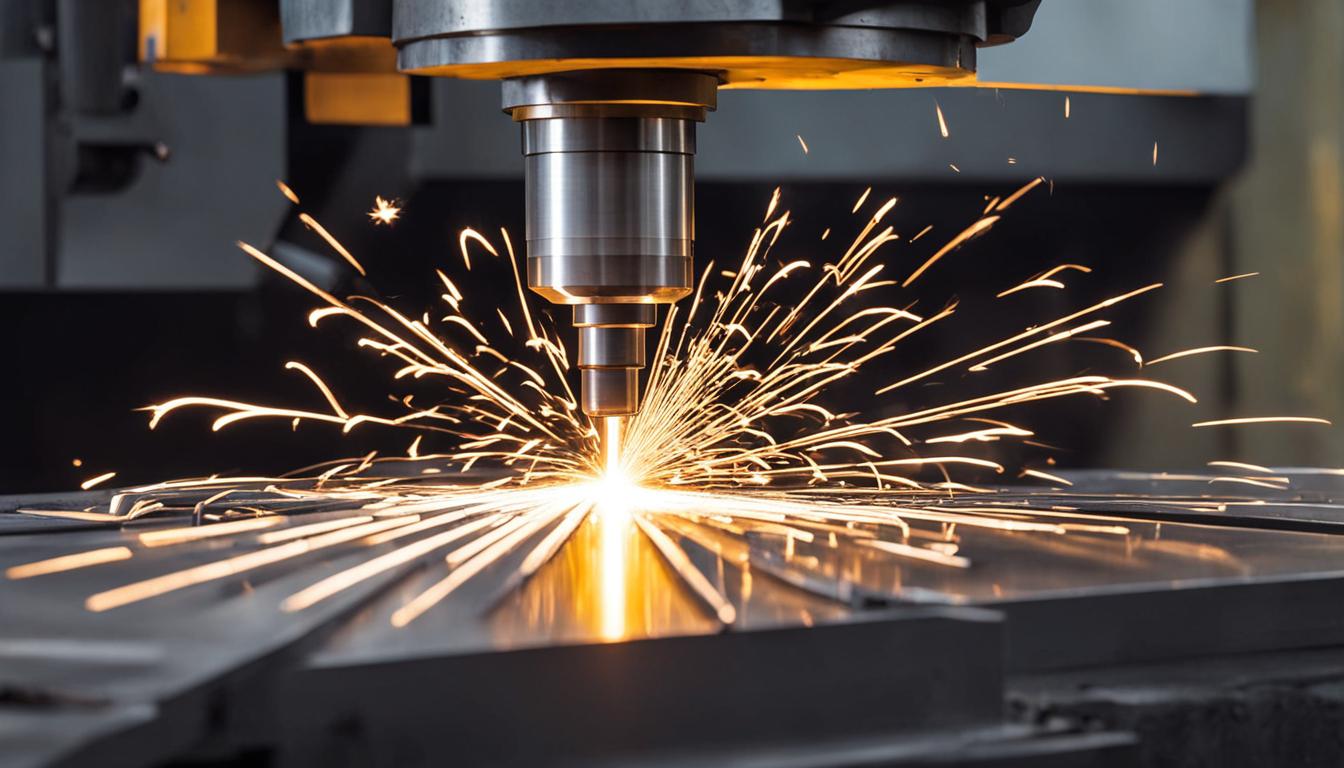
CNC machining mild steel is a common and highly effective practice in modern manufacturing, leveraging the material’s inherent machinability and cost-effectiveness. Mild steel, typically represented by AISI 1018, is a low-carbon steel alloy known for its balanced strength, ductility, and predictable behavior during cutting operations. Its low carbon content, generally between 0.05% and 0.25%, contributes to its flexibility and ease of fabrication, making it a versatile choice for a wide array of components, from structural elements to precision parts.
The machinability of AISI 1018 is rated between 62% and 78% compared to AISI 1112 or 1212, which are benchmarks for 100% machinability. This characteristic, combined with its soft ferritic/pearlitic microstructure, allows for efficient material removal, good surface finishes, and reduced wear on cutting tools, particularly when using cold-rolled variants. Understanding the properties of mild steel is the first step toward optimizing CNC processes for this ubiquitous material.
Fe-Based Metal Machining Fundamentals
Mild steel, a ferrous alloy, presents a favorable machining profile due to its relatively low hardness and good ductility. These properties allow for consistent chip formation and lower cutting forces compared to higher-carbon or alloy steels. However, its ductility can also lead to continuous, stringy chips if not properly managed, which can impede chip evacuation and affect surface finish. Effective machining strategies must account for these characteristics to ensure optimal results.
Common mild steel grades like AISI 1018 and AISI 1020 are frequently selected for CNC machining due to their excellent balance of mechanical properties and ease of processing. These materials are ideal for applications requiring moderate strength and good weldability, such as shafts, pins, fixtures, and general engineering components. Cold-drawn 1018, in particular, offers tighter dimensional consistency and a cleaner surface, making it suitable for precision parts where close tolerances are specified.
Standard CNC machining tolerances for mild steel typically range from ±0.005 inches (±0.13 mm) for general dimensions. For more critical features, precision tolerances can be tightened to ±0.002 inches (±0.051 mm), and even ±0.0005 inches (±0.0127 mm) for reamed holes. Achieving these tighter tolerances often requires careful control of machining parameters and a highly rigid setup, which can influence production costs and lead times. The ISO 2768 standard, particularly ISO 2768-1 for linear and angular dimensions, provides a globally recognized framework for general tolerances in mild steel machining.
Solid Carbide Coated End Mills
| Parameter | Solid Carbide End Mill (Coated) | HSS End Mill (Uncoated) |
|---|---|---|
| Surface Speed (SFM) | 250 – 550 | 80 – 120 |
| Chip Load (IPT) for 1/2″ End Mill | 0.0015″ – 0.003″ | 0.002″ – 0.004″ |
| Typical Flute Count | 4 or more | 2-4 |
Solid carbide end mills are the preferred tooling choice for CNC machining mild steel, offering superior hardness and wear resistance over high-speed steel (HSS) tools. The performance of these tools is significantly enhanced by advanced coatings, which serve to extend tool life, reduce friction, and allow for higher cutting speeds and feeds. These coatings are typically applied through Physical Vapor Deposition (PVD) processes, which create thin, tough layers without compromising the tool’s edge integrity.
Titanium Aluminum Nitride (TiAlN) is a highly effective coating for machining mild steel, providing exceptional wear resistance and high-temperature stability. This PVD coating enables tools to operate at elevated cutting temperatures, even in dry machining conditions, and can dramatically increase tool life compared to uncoated alternatives. TiAlN is a versatile choice, performing well across various steels, stainless steels, and cast iron.
Other beneficial coatings include Titanium Nitride (TiN), a general-purpose coating that reduces friction and increases tool life in standard-speed cutting of mild steels and non-ferrous materials. Titanium Carbonitride (TiCN) offers enhanced hardness and lubricity, making it suitable for applications involving high abrasive wear. Aluminum Chromium Nitride (AlCrN) and its advanced variants like AlTiN Nano are also excellent for high-heat applications and hardened steels, further extending tool performance.
End mill geometry is equally critical for efficient mild steel machining. Tools with four or more flutes are often favored for steel, as the increased flute count enhances core rigidity, which supports higher feed rates and improves surface finishes. Helix angles typically range from 30° to 60°, with a medium helix (30°-40°) providing a good balance between chip evacuation and edge strength, while a 38° helix angle is often a practical compromise for both roughing and finishing operations.
Rigid Machine Setup Requirements
A highly rigid machine setup is non-negotiable for achieving precision and efficiency when CNC machining mild steel. The entire machining system, often referred to as the ‘rigidity chain,’ must be optimized to effectively counteract cutting forces and minimize vibrations. This chain includes the machine’s structural components, the tool holder, the cutting tool itself, the workholding solution, and the workpiece. Any compromise in this chain can lead to detrimental effects such as chatter, poor surface finish, premature tool wear, and dimensional inaccuracies.
The foundational element is the machine’s structural integrity, which requires a robust frame and a stable machine bed to absorb vibrations and maintain accuracy during aggressive cuts. While a heavier machine often correlates with increased rigidity, it is important to recognize that spindle design, motion control system accuracy, guide rail quality, and thermal stability are equally significant factors contributing to overall machining performance. For milling steel, machines ideally exhibit a rigidity of 20-30 Nm/µm deflection, with high-performance machines exceeding 70 Nm/µm.
Workholding is a critical aspect of maintaining rigidity, ensuring the workpiece remains immovably secured against the dynamic forces generated during machining. Vises are a common and effective solution for clamping block-shaped parts, while specialized clamps, magnetic fixtures, or bolted setups provide robust gripping for various part geometries. Proper workholding practices include positioning clamps clear of the toolpath, applying even clamping pressure, and utilizing multiple contact points to prevent any lifting or warping of the workpiece.
Tool holding significantly influences the overall rigidity and precision of the cutting process. Minimizing the tool’s stick-out length is crucial, as tool rigidity diminishes exponentially with increased unsupported length. High-quality tool holders that exhibit minimal runout are essential; most precision machining applications target a Total Indicating Runout (TIR) of less than 0.0002–0.0005 inches at the tool tip. Excessive runout leads to uneven chip loads on cutting edges, accelerating tool wear, increasing the risk of breakage, and degrading surface quality.
Maintaining the spindle and its precision bearings is another vital aspect of machine rigidity. Spindle bearings are critical, high-stress components whose failure can result in costly downtime and compromised part quality. Regular monitoring for unusual noises, excessive vibrations, and abnormal temperature fluctuations is paramount for early detection of issues. Adhering to proper lubrication schedules, ensuring a clean and dry air supply, and implementing spindle warm-up routines are all essential practices that extend bearing life and preserve spindle accuracy.
Optimizing Coolant and Chip Flushing
Effective coolant and chip flushing are indispensable for successful CNC machining of mild steel, directly influencing heat management, tool longevity, and the quality of the machined part. The intense friction generated during metal cutting produces significant heat, which, if not properly dissipated, can lead to rapid tool wear, the formation of built-up edge, and compromised surface finishes. Coolants also provide crucial lubrication to the cutting zone and facilitate the efficient evacuation of chips, preventing re-cutting and potential damage to both the workpiece and the cutting tool.
For mild steel applications, water-soluble and semi-synthetic coolants are widely favored due to their balanced properties of cooling, lubrication, and corrosion protection. These fluids are typically diluted with water and contain various additives designed to enhance performance, inhibit bacterial growth, and minimize foaming. Regular monitoring of coolant concentration using a refractometer and diligent skimming of tramp oil are essential maintenance practices that ensure optimal coolant performance and extend its service life.
High-pressure coolant (HPC) systems, which deliver fluid at pressures ranging from 500 to 2,000+ PSI, dramatically enhance chip evacuation and cooling efficiency. HPC effectively penetrates the vapor barrier that forms at the cutting interface, directly cooling the tool-chip contact point and making chips more brittle, which facilitates their breakage and removal. This aggressive cooling and chip management capability translates into extended tool life, increased cutting speeds, superior chip control, and improved surface finishes.
Through-spindle coolant (TSC) represents a highly effective method for delivering high-pressure coolant directly to the cutting edge, proving particularly advantageous for deep hole drilling and pocketing operations where conventional flood coolant struggles to reach. TSC prevents chips from packing in the tool flutes, significantly reduces chip re-cutting, and ensures consistent cooling, all of which are critical for maintaining dimensional accuracy and achieving a high-quality surface finish. While flood coolant remains suitable for many general milling tasks, TSC offers a distinct performance advantage in demanding applications by maximizing chip removal and targeted cooling precisely where it is most needed.
Calculating Speeds and Feeds for Mild Steel
Accurate calculation of speeds and feeds is paramount for successful CNC machining of mild steel, directly influencing tool life, surface finish, and overall productivity. These critical parameters, specifically Surface Feet per Minute (SFM) and Chip Load per Tooth (Fz or IPT), must be meticulously selected based on the workpiece material, the cutting tool material, and the rigidity of the machine setup. Operating with insufficient chip load can lead to rubbing instead of cutting, causing premature tool wear, while excessive speeds can result in the thermal degradation of the cutting edge.
For mild steel, such as AISI 1018, coated solid carbide end mills are capable of operating at significantly higher surface speeds compared to High-Speed Steel (HSS) tools. A typical starting range for carbide in 1018 mild steel is 250–550 SFM, whereas HSS tools might operate at 80–120 SFM. This substantial difference in cutting speed is primarily attributed to carbide’s superior hardness retention at elevated temperatures and its inherently greater stiffness, which minimizes tool deflection during aggressive cutting.
Chip load per tooth (Fz) defines the precise thickness of material that each cutting flute removes during a single spindle revolution. For a 4-flute carbide end mill machining mild steel, a recommended chip load typically falls within the range of 0.001″ to 0.003″ per tooth, with specific values varying based on the tool’s diameter. Maintaining an optimal chip load is crucial for generating healthy, comma-shaped chips that efficiently absorb and carry heat away from the cutting zone, preventing thermal damage to the tool and workpiece.
The fundamental formulas for calculating spindle speed (RPM) and feed rate (IPM or mm/min) are essential for programming CNC machines:
- Spindle Speed (RPM) = (Surface Speed (SFM) × 3.82) / Tool Diameter (inches)
- Feed Rate (IPM) = Spindle Speed (RPM) × Chip Load (IPT) × Number of Flutes
For metric system calculations, the formulas are:
- Spindle Speed (RPM) = (Cutting Speed (m/min) × 1000) / (π × Tool Diameter (mm))
- Feed Rate (mm/min) = Spindle Speed (RPM) × Chip Load (mm/tooth) × Number of Flutes
These calculations provide a robust starting point, but practical fine-tuning is often necessary based on observed chip morphology, audible feedback from the machining process, and the available power headroom of the machine. Additionally, phenomena such as chip thinning, which occurs when the radial engagement of the cutter is less than 50% of its diameter, may require adjustments to the programmed feed rate to ensure the effective chip thickness remains within the desired range.
This table offers general guidelines; always consult specific tool manufacturer recommendations for optimal performance.