
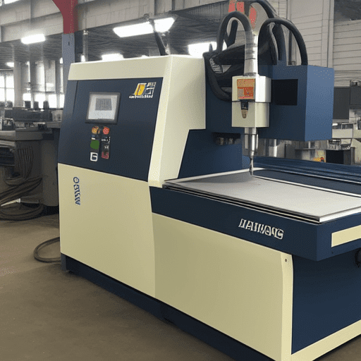
A Computer Numerical Control (CNC) milling machine fundamentally comprises two primary, interdependent systems: the control unit and the machine body. These components work in concert, translating digital instructions into precise physical movements to shape raw materials. Understanding their individual functions and intricate interactions is essential for optimizing machining performance and maintaining operational integrity.
The control unit acts as the machine’s ‘brain,’ interpreting complex G-code programs and generating the necessary signals to drive the mechanical elements. Simultaneously, the machine body provides the robust physical platform, housing the spindle, workpiece table, and the intricate mechanical drives that execute the programmed tool paths with high accuracy.
The Central Nervous System: CNC Control Unit (MCU)
The CNC Control Unit, or Machine Control Unit (MCU), serves as the computational core of any CNC milling machine. It processes part programs, typically written in G-code, and translates them into electrical signals that command the machine’s axes and spindle. Modern MCUs, such as those from Fanuc, Siemens, and Haas, offer varying levels of sophistication and market prevalence.
These controllers integrate a processor, memory, and input/output (I/O) interfaces to manage the entire machining process. Fanuc, for instance, holds over 65% of the global market share, known for its reliability and standard G-code compatibility. Siemens Sinumerik controls are prominent in Europe, excelling in complex 5-axis and multi-channel applications, while Haas offers user-friendly, Fanuc-compatible interfaces ideal for many job shops.
The MCU’s software interprets G-code commands, performing critical functions like interpolation. Interpolation algorithms calculate the intermediate points between programmed coordinates, generating smooth, continuous tool paths for linear, circular, and even helical movements. This real-time calculation is vital for achieving the desired part geometry and surface finish.
Beyond motion control, the MCU manages feeds and speeds, tool changes, coolant flow, and safety interlocks. Advanced controllers often include features like thermal compensation and real-time vibration suppression, enhancing machining accuracy and extending tool life.
The Physical Foundation: Machine Body and Spindle/Table Assembly
| Feature | Servo Motor | Stepper Motor |
|---|---|---|
| Control Type | Closed Loop (with feedback) | Open Loop (typically, no feedback) |
| Feedback Mechanism | Encoder or Resolver | None (position inferred from pulses) |
| High-Speed Torque | Stable, high torque maintained | Drops significantly at higher speeds |
| Accuracy & Stability | High, real-time error correction | Moderate, prone to missed steps under load |
| Acceleration | Strong, dynamic response | Limited, less dynamic |
| Cost | Higher initial investment | Lower initial investment |
| Typical Applications | High-precision CNC, robotics, automation | 3D printing, basic positioning, lower-speed tasks |
The machine body provides the structural rigidity and stability necessary for precision machining. Constructed from materials like cast iron or polymer concrete, its mass and dampening characteristics are crucial for absorbing vibrations generated during cutting, which directly impacts surface finish and tool life. The overall design ensures the precise alignment of all mechanical components.
Integrated within this structure are the spindle and the workpiece table. The spindle, a critical component, holds the cutting tool and rotates it at high speeds, often ranging from a few thousand to over 20,000 RPM, depending on the application and material. Spindle power ratings vary significantly, from a few horsepower for smaller machines to over 50 HP for heavy-duty milling centers. Tooling interfaces, such as BT, CAT, or HSK, ensure secure and repeatable tool clamping.
The machine table, typically equipped with T-slots, provides a secure platform for mounting workholding devices and the workpiece itself. Its flatness and perpendicularity to the spindle axis are fundamental geometric tolerances that directly influence the accuracy of machined features. Maintaining these tolerances is paramount for consistent part quality.
Mechanical Drive Interaction: Precision in Motion
The mechanical drive system translates the MCU’s electrical signals into controlled linear or rotary motion. This system primarily consists of motors, ball screws, and linear guides. Servo motors are widely preferred in modern CNC milling for their closed-loop control, providing continuous feedback on position, speed, and torque, which allows for real-time error correction.
Stepper motors, while simpler and more cost-effective, operate in an open-loop system without direct position feedback, making them suitable for less demanding applications where small errors are acceptable. Servo systems offer superior acceleration and maintain torque at high speeds, crucial for dynamic contouring and complex geometries.
Ball screws convert the rotary motion of the motors into precise linear motion along each axis. Their accuracy is defined by precision classes, ranging from C0 (highest) to C10 (lowest), with tighter tolerances reducing lead error. Backlash, the play between the ball nut and screw shaft, is a critical concern, often mitigated by preloaded ball nuts or electronic compensation in the MCU.
Linear guides, such as profiled rail guides or roller guides, support the moving components (table, saddle, headstock) and ensure smooth, low-friction travel. These guides are selected based on required load capacity, speed, and accuracy, directly impacting the machine’s ability to maintain precise tool paths and achieve tight tolerances.
Electrical System Control: Powering Precision
The electrical system provides the necessary power and control signals for all machine functions, acting as the interface between the MCU and the mechanical components. It includes power supply units (PSUs), motor drivers/amplifiers, and various sensors. PSUs convert incoming AC power to the DC voltages required by the control electronics and motors.
Motor drivers, or servo amplifiers, receive low-voltage control signals from the MCU and convert them into high-power electrical currents to drive the servo or stepper motors. These drivers are critical for precise motor control, including acceleration, deceleration, and maintaining commanded speeds and positions.
Effective electromagnetic interference (EMI) and radio-frequency interference (RFI) shielding is paramount in CNC electrical systems. Shielded cables for motor wiring, limit switches, and signal lines prevent electrical noise from causing erratic machine behavior or inaccuracies. Proper grounding, often in a ‘star’ configuration, is essential to dissipate noise and ensure signal integrity.
Safety interlocks, limit switches, and emergency stop circuits are integrated into the electrical system to protect operators and the machine. These components provide critical feedback to the MCU, immediately halting operations if a safety condition is violated or a mechanical limit is reached.
Axis Motion Coordination: Orchestrating Movement
Axis motion coordination is the MCU’s ability to precisely synchronize the movement of multiple axes simultaneously, which is fundamental for generating complex geometries. In 3-axis milling, the X, Y, and Z axes move in a coordinated fashion. More advanced machines, like 5-axis mills, add rotary axes (A, B, or C) for even greater flexibility and part complexity.
Closed-loop control systems are vital for achieving high accuracy and repeatability. These systems utilize feedback devices, such as encoders mounted on motors or linear scales directly on the machine axes, to continuously monitor the actual position of each moving component.
The MCU compares this real-time feedback with the commanded position. Any deviation, or ‘error,’ triggers immediate corrective action by the motor drivers, ensuring the tool follows the programmed path with minimal deviation. This continuous feedback loop compensates for factors like load changes, mechanical backlash, and thermal expansion.
Machine tool accuracy and repeatability are quantified by international standards like ISO 230-2 and ISO 230-4. ISO 230-2 specifies methods for testing the positioning accuracy and repeatability of numerically controlled axes, while ISO 230-4 addresses the contouring performance through circular tests.
Standard CNC machining tolerances typically range from ±0.005″ (±0.127 mm) for general features to ±0.001″ (±0.025 mm) for precision applications, with tighter tolerances requiring slower feed rates and meticulous setup.