
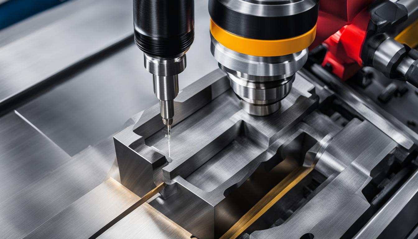
Manufacturing relies on various processes to transform raw materials into finished components. At its fundamental level, material removal, or machining, primarily categorizes into two distinct approaches: conventional manual machining and Computer Numerical Control (CNC) automated machining. Each method offers unique advantages and is suited for different production requirements and precision demands.
Conventional Manual Machining
Conventional manual machining involves direct human operation of machine tools such as lathes, mills, and grinders. Skilled machinists control the cutting tools and workpiece movement using handwheels, levers, and visual feedback. This hands-on approach demands significant expertise and craftsmanship from the operator.
This method is particularly advantageous for low-volume production, one-off prototypes, and repair work where setup time and programming costs for automated systems would be prohibitive. Manual machines offer maximum flexibility for on-the-fly design tweaks and quick adjustments during the machining process.
Typical tolerances achievable with conventional manual machining generally range from ±0.001 to ±0.005 inches (±0.025 mm to ±0.127 mm), depending heavily on the machinist’s skill, machine condition, and material. While experienced operators can achieve tighter tolerances, maintaining consistency across multiple parts is challenging.
For example, when turning 1045 steel on a manual lathe, a machinist might use a surface feet per minute (SFM) of around 200 and a feed rate of 0.006 inches per revolution (IPR) for finishing passes with a 0.01-inch depth of cut. This requires constant attention and adjustment to achieve the desired surface finish and dimensional accuracy.
CNC Automated Machining
| Characteristic | Cutting Tool Methods | Abrasive Methods |
|---|---|---|
| Material Removal Mechanism | Defined cutting edges shear chips | Undefined abrasive particles grind/rub |
| Typical Surface Finish (Ra) | 1.6 – 6.3 µm (63 – 250 µin) | 0.025 – 1.6 µm (1 – 63 µin) |
| Material Hardness Suitability | Softer to moderately hard materials | Hardened steels, ceramics, brittle materials |
| Dimensional Tolerance | ±0.001″ to ±0.005″ (CNC tighter) | ±0.0001″ to ±0.0005″ (often finer) |
| Tool Examples | End mills, drills, turning inserts | Grinding wheels, honing stones, abrasive slurries |
CNC automated machining utilizes computer software to control the precise movements of machine tools. Digital instructions, often generated from CAD/CAM software and translated into G-code, dictate every aspect of the machining process, including tool paths, speeds, and feeds. This automation significantly reduces human error and enhances repeatability.
Modern CNC machines, including mills, lathes, routers, and multi-axis systems, can produce intricate and complex geometries that are difficult or impossible with manual methods. They are ideal for high-volume production where consistent quality and rapid output are critical.
Precision CNC machining typically achieves tighter tolerances, often ranging from ±0.001 inches (±0.0254 mm) for standard applications to as fine as ±0.0001 inches (±0.0025 mm) or even 1-3 microns for critical aerospace and medical components. This level of accuracy is maintained consistently across large production batches.
Current trends in CNC machining for 2026 emphasize AI-native control, digital twins, hybrid manufacturing, and increased automation with robotics. These advancements aim to optimize toolpaths, predict maintenance needs, and integrate additive and subtractive processes for greater efficiency and complexity.
For instance, when CNC milling 6061 aluminum with a carbide end mill, recommended starting parameters include surface feet per minute (SFM) between 800 and 1,000, with a chip load of 0.003 to 0.005 inches per tooth for a 1/4-inch end mill. High-speed machining (HSM) strategies, involving full-depth, light-radial passes at high feed rates, are particularly effective for maximizing material removal rates.
Subtractive Material Processes
Subtractive manufacturing encompasses any process that removes material from a workpiece to create a desired shape. This category includes all forms of machining, where material is systematically cut away, drilled, milled, or ground. The removed material typically becomes chips or swarf, representing waste.
This approach contrasts sharply with additive manufacturing, such as 3D printing, which builds objects layer by layer. Subtractive processes are generally favored for achieving high dimensional accuracy, superior surface finishes, and for working with a wide range of engineering materials, including metals, plastics, and composites.
Material removal efficiency and chip control are critical considerations in subtractive processes. Proper selection of cutting tools, feeds, speeds, and coolants directly impacts tool life, surface integrity, and overall production cost. Optimizing these parameters minimizes waste and maximizes throughput.
Cutting Tool vs. Abrasive Methods
Within subtractive manufacturing, material removal primarily occurs through two distinct mechanisms: cutting with defined geometry tools or abrasive methods using undefined geometry particles. Each method is chosen based on the workpiece material, required precision, and surface finish specifications.
Cutting tools, such as end mills, drills, and turning inserts, feature defined cutting edges that shear material in the form of chips. These tools are typically made from materials like high-speed steel, cemented carbides, ceramics, or cubic boron nitride, selected for their hardness, toughness, and wear resistance.
Abrasive methods, conversely, utilize numerous small, hard particles, often aluminum oxide, silicon carbide, or diamond, to remove material through grinding, rubbing, and plowing actions. These particles can be bonded into wheels (e.g., grinding wheels) or used as loose abrasives in slurries (e.g., lapping, honing, abrasive flow machining).
Abrasive processes are particularly effective for machining hardened materials, achieving extremely fine surface finishes, and producing complex internal geometries or precise forms that cutting tools might struggle with. Examples include surface grinding, cylindrical grinding, honing, lapping, and abrasive waterjet cutting.
Primary Manufacturing Classifications
Machining, whether manual or automated, fits into a broader framework of primary manufacturing classifications. These categories define the fundamental ways raw materials are processed into useful forms. Understanding these distinctions provides context for the role of machining in industrial production.
Manufacturing processes are generally categorized into several key areas: forming, joining, additive, subtractive, and casting. Each classification represents a distinct approach to material manipulation, often involving different energy sources, tooling, and material states.
Forming processes, such as forging, stamping, and bending, reshape materials without removing chips or adding material, typically by applying force. Joining processes, including welding, brazing, and fastening, permanently or semi-permanently connect multiple components. Additive manufacturing, exemplified by 3D printing, builds objects layer by layer from digital models. Casting involves pouring molten material into a mold to solidify into a desired shape.
Subtractive manufacturing, which encompasses all machining operations, remains indispensable for achieving high precision, tight tolerances, and specific surface finishes required across industries like aerospace, medical devices, and automotive. Its ability to work with a vast array of materials ensures its continued relevance in modern engineering.