
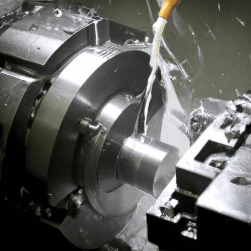
Producing components with exacting specifications on a CNC lathe demands a meticulous approach to machine selection, workholding, support, measurement, and cutting tool technology. Achieving tight tolerances, often in the micron range, requires a synergistic combination of advanced equipment and refined machining practices. The foundation for such precision begins with the inherent capabilities of the turning center itself.
Precision CNC Lathes: the Foundation of Accuracy
Modern CNC lathes are engineered for exceptional rigidity and thermal stability, crucial factors in maintaining dimensional accuracy during prolonged machining cycles. These machines feature robust cast iron or polymer concrete bases that absorb vibrations, preventing chatter and ensuring consistent surface finishes. High-precision linear guideways and ball screws, often paired with direct-drive servo motors, provide sub-micron positioning accuracy.
Advanced control systems on these lathes incorporate thermal compensation, actively adjusting for slight dimensional changes caused by temperature fluctuations in the machine components. This proactive compensation is vital for holding tolerances as tight as ±0.001 inches (±0.025 mm) or even better, which is a common requirement in aerospace and medical device manufacturing.
Spindle runout, a critical parameter for precision, is meticulously controlled in high-end CNC lathes. Acceptable radial runout specifications for precision machining centers typically fall within 5-10 micrometers (0.0002-0.0004 inches) for precision/mill-tolerance VMCs, and even tighter for high-speed HSK spindles.
Workholding for Precision: Collet Chuck Systems
| Component | Typical Precision Specification | Relevant Standard/Metric |
|---|---|---|
| Precision CNC Lathe | ±0.001 inches (±0.025 mm) or better | ISO 2768-1 Fine (f), Spindle Runout (TIR) |
| 5C Collet System | ≤0.0002 inches (≤0.005 mm) TIR | Total Indicator Runout (TIR) |
| ER Collet System | ≤0.0004 inches (≤10 µm) TIR (High-Precision) | DIN 6499 / ISO 15488 |
| Live Center Support | ≤0.00005 inches (≤0.00127 mm) TIR | Total Indicator Runout (TIR) |
| Dial Indicator Resolution | 0.0001 inches (0.001 mm) | Graduation Value |
Collet chuck systems are indispensable for precision turning due to their superior concentricity and uniform clamping force compared to traditional three-jaw chucks. Collets provide 360-degree contact around the workpiece, minimizing runout and preventing part deformation, especially with delicate or thin-walled components.
The ‘5C’ collet system, for instance, is a widely used solution known for its versatility and precision, accommodating round stock from 1/64″ to 1-1/8″ diameter. Special accuracy 5C collets can achieve a maximum Total Indicator Runout (TIR) of 0.0002 inches (0.005 mm) when held in a super-precision spindle.
ER collets, standardized under DIN 6499 / ISO 15488, are another prevalent type, offering a clamping range typically within 1 mm of their nominal size. High-precision ER collets can achieve runout within 10 micrometers (0.0004 inches), with some precision collets rated to 3 micrometers (0.00012 inches). Proper collet selection, ensuring the workpiece diameter matches the collet’s nominal size within tight tolerances, is paramount for optimal accuracy.
Ensuring Concentricity: Live Center Support
For turning longer or heavier workpieces, a live center provides essential support at the non-driven end, preventing deflection, vibration, and chatter. This support is critical for maintaining dimensional accuracy and achieving desired surface finishes, particularly when operating at higher cutting speeds.
Live centers feature a hardened steel point that rotates with the workpiece on high-precision bearings, minimizing friction and heat generation. Standard live centers often offer runout of ≤0.00005 inches (≤0.00127 mm) TIR, with some precision models achieving ≤0.00003 inches (≤0.00076 mm) TIR. Heavy-duty CNC spindle-type live centers are guaranteed accurate to ±0.00005 inches TIR or better.
Selecting the appropriate live center involves considering factors such as workpiece weight, RPM, and material type. Advanced designs incorporate dual-ball-bearing thrust systems with micrometer-level adjustment, allowing for fine-tuning of pressure to compensate for thermal expansion and reduce radial play. This meticulous attention to support directly impacts tool life and part quality.
Verifying Precision: the Role of Dial Indicators
Dial indicators are fundamental metrology instruments used extensively in precision turning for setup, alignment, and verification of dimensional variations. They convert small linear displacements into a magnified rotational movement on a graduated dial, enabling precise readings.
Common dial indicators have a resolution of 0.001 inches (0.01 mm), while high-precision models can achieve resolutions as fine as 0.0001 inches (0.001 mm) or even 0.00005 inches. It is important to distinguish between resolution and accuracy; a 0.0001-inch indicator resolves smaller increments, but its overall accuracy is determined by calibration and internal mechanism quality, typically ±0.001 inches over its full range for AGD-grade mechanical indicators.
For critical precision work, dial indicators with 0.0001-inch graduation are reserved for tolerance bands tighter than ±0.001 inches. These instruments are crucial for checking spindle runout, workpiece concentricity in chucks or collets, and parallelism during machine setup, ensuring that all components are aligned to minimize Total Indicator Runout (TIR).
Cutting Edge Performance: Ground Carbide Inserts
Ground carbide inserts are essential for achieving the superior surface finishes and tight dimensional accuracies required in precision turning. Unlike molded inserts, ground inserts feature sharper, more precise cutting edges and geometries, which are critical for minimizing cutting forces and improving chip control. The grinding process ensures consistent edge preparation, leading to predictable tool wear and repeatable part quality.
Modern carbide inserts are often enhanced with advanced coatings, such as Physical Vapor Deposition (PVD) or Chemical Vapor Deposition (CVD). PVD coatings, typically 1-5 microns thick, preserve sharp edges and fine geometries, making them ideal for precision finishing, stainless steel, and heat-resistant alloys. CVD coatings, being thicker, offer maximum wear resistance in continuous cutting and high heat resistance, suitable for roughing steel and cast iron.
Selecting the correct insert grade, geometry, and coating is paramount for optimizing feeds and speeds. For precision finishing, lower feed rates (0.05–0.15 mm/rev) are typically employed to achieve desired surface finishes and tolerances. Cutting speeds for carbide inserts in mild steel can range from 700 to 1700 SFM, depending on the specific grade and coating, with aluminum often allowing for even higher speeds. Always consult the insert manufacturer’s datasheet for specific recommendations tailored to the material and application.