
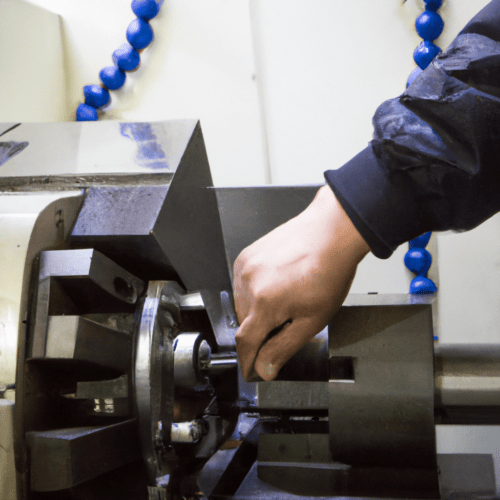
Computer Numerical Control (CNC) machining represents an automated manufacturing process that precisely controls machine tools through pre-programmed computer software. This technology has fundamentally transformed industrial fabrication by enabling the production of custom parts and components with exceptional accuracy and efficiency. CNC systems eliminate the need for manual operator control, enhancing consistency and repeatability in production.
CNC machines execute pre-programmed sequences of commands, guiding tools like mills, lathes, and drills to perform specific tasks. This automation streamlines the manufacturing process, allowing for complex operations with minimal human intervention.
Computer Numerical Control: the Core Definition
CNC, or Computer Numerical Control, refers to the computerized operation of machining tools in manufacturing. It involves using software and codes to dictate the exact movements and tasks a machine must complete. This digital control system allows machines to cut, manipulate, and create goods from various materials without direct manual guidance.
The roots of numerical control systems emerged in the mid-20th century, driven by the aviation industry’s need for more efficient and precise machining of complex aircraft components. Early systems relied on punched tape, which evolved into today’s sophisticated computer-based programming. Modern CNC systems offer expansive computational capacity, with programs retained in computer memory and easily edited.
Subtractive Fabrication: Material Removal Principles
| Parameter | Typical 6061 Aluminum (Carbide End Mill) | Typical 1018 Steel (Carbide End Mill) |
|---|---|---|
| Cutting Speed (SFM / m/min) | 1000-4000 SFM (300-1200 m/min) | 450-800 SFM (137-244 m/min) |
| Chip Load (per tooth) | 0.002″-0.010″ (0.05-0.25 mm) | 0.003″-0.008″ (0.07-0.20 mm) |
| Spindle Speed (RPM) | 6,000-20,000 RPM (varies with tool diameter) | 2,292-7,000 RPM (varies with tool diameter) |
| Axial Depth of Cut (Roughing) | Up to ~3 mm (0.12″) | Up to ~1.5″ (38 mm) with adaptive roughing |
| Surface Finish (Ra) | Excellent, often <1.6 µm (63 µin) | Easily achievable Ra 1.6 µm (63 µin) |
Subtractive manufacturing encompasses processes that form parts by removing material from a solid block, billet, or sheet. This method contrasts sharply with additive manufacturing (3D printing), which builds objects layer by layer. In subtractive processes, material is precisely cut away through operations such as drilling, milling, turning, boring, or grinding.
Engineers often begin with a Computer-Aided Design (CAD) model, which is then converted into Computer-Aided Manufacturing (CAM) toolpaths. These toolpaths generate G-code, directing the machine’s movements to remove material. Subtractive methods are favored for their ability to deliver tight tolerances, superior surface finishes, and reliable material performance.
Automated Machine Tools: the Hardware Foundation
CNC machines rely on several automation components to function efficiently and precisely. Key elements include servo motors for precise motion control, ball screws for converting rotational motion into linear movement, and linear guides for stable and accurate axis positioning. These components work in concert to ensure smooth and repeatable operations.
Modern CNC machining centers often integrate advanced features such as tool magazines for automatic tool changes, automatic tool length measurement systems, and chip conveyors to manage debris. Pallet changers can further automate the process by exchanging workpieces, enabling continuous machining without manual intervention.
Common types of CNC machines include milling machines, which use rotating cutting tools for diverse 3D shapes; lathes, which rotate the workpiece for cylindrical parts; and routers, typically used for softer materials like wood and plastics. More advanced machines can feature five or more axes, allowing for highly intricate and complex geometries.
Digital 3D Model Execution: from Design to Part
The journey from a digital 3D model to a physical part in CNC machining begins with Computer-Aided Design (CAD) software. Designers create accurate 3D models, ensuring all dimensions, angles, and tolerances meet specifications. This CAD model serves as the foundational data for the entire manufacturing process.
Next, Computer-Aided Manufacturing (CAM) software translates the CAD model into machine-readable instructions, primarily G-code and M-code. G-code controls the geometric movements of the machine tool, dictating paths, speeds, and positions. M-code manages miscellaneous machine functions, such as spindle start/stop, coolant activation, and tool changes.
Before physical production, CAM software often performs simulations to verify toolpaths and identify potential errors, reducing scrap and optimizing cycle times. The generated G-code is then fed to the CNC controller, which executes the program, guiding the machine tools to precisely remove material from the workpiece. This digital workflow ensures high accuracy and consistency.
Achieving High Precision Manufacturing
High precision manufacturing in CNC machining involves producing components with extremely tight dimensional tolerances and consistent repeatability. This level of precision is critical for parts that must fit perfectly, function predictably, and perform reliably under stress, such as those in aerospace, medical, and automotive industries.
Machining tolerances define the permissible limits of variation in a part’s physical dimension. International standards like ISO 2768 and ASME Y14.5 provide frameworks for specifying these tolerances. ISO 2768 offers general tolerances for linear and angular dimensions when specific callouts are absent, simplifying drawings for non-critical features.
For critical features requiring greater accuracy, ASME Y14.5, or ISO 286, are employed, often utilizing Geometric Dimensioning and Tolerancing (GD&T) to control form, orientation, and location. Achieving high precision often necessitates slower machining speeds, more frequent tool changes, and rigorous quality checks, which can impact lead time and cost.
Modern CNC technology enhances accuracy through advanced programming, automation, and real-time monitoring of tool wear and surface finish. Digital twins and AI-based systems are increasingly integrated to optimize processes, predict tool wear, and detect defects, further pushing the boundaries of achievable precision.
Standard machining tolerances typically range around ±0.005 inches (±0.13 mm) for metals, suitable for general-purpose parts and prototypes. For applications demanding higher accuracy, precision tolerances can be as tight as ±0.002 inches (±0.051 mm), with reamed holes achieving ±0.0005 inches (±0.0127 mm).