
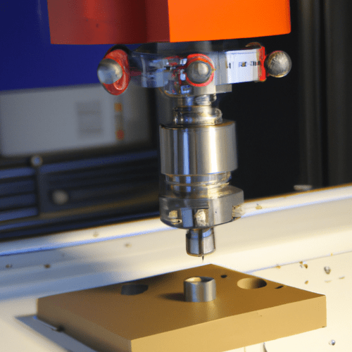
2.5D milling represents a fundamental and widely utilized machining process, bridging the gap between basic 2D cutting and complex 3D contouring. This method involves cutting a three-dimensional object where all features are essentially projections of a plane, meaning no overhanging elements are possible. It is particularly effective for creating parts with multiple flat surfaces at varying depths, often referred to as ‘prismatic parts’.
This machining approach is executed on standard 3-axis CNC machines, which possess the capability to translate in all three axes (X, Y, and Z). However, during a 2.5D operation, the cutting action occurs primarily in two axes simultaneously, typically X and Y, while the Z-axis moves in discrete, stepped increments between cuts.
Simultaneous 2-Axis Control
Simultaneous 2-axis control is a defining characteristic of 2.5D milling, where the cutting tool moves continuously along two axes, most commonly X and Y, to define the shape of a feature. This coordinated movement allows for the creation of intricate profiles, slots, and pockets on a single plane. The tool maintains a constant depth during these XY plane movements.
This synchronized motion is crucial for generating smooth curves and precise linear paths within a given layer of material. Controllers manage these movements by interpreting G-code instructions, coordinating the X and Y axes to follow the programmed toolpath accurately.
While the X and Y axes move in unison, the Z-axis remains stationary at a specific depth for the duration of that particular cutting pass. This distinction is what separates 2.5D from true 3D machining, where all three axes can move simultaneously to create continuously contoured surfaces.
Z-Axis Stepped Movement
| Parameter | Typical Range | Notes |
|---|---|---|
| Standard Tolerance | ±0.05 mm to ±0.1 mm | For non-critical features. |
| Precision Tolerance | ±0.01 mm to ±0.025 mm | Achievable with specialized equipment and controlled conditions. |
| Surface Speed (SFM) | 800-1,000 SFM | For carbide tooling in 6061-T6 aluminum. |
| Chip Load per Tooth | 0.002-0.004 inch | For a 1/4 inch, 2 or 3 flute end mill in 6061-T6. |
| Feed Rate (Hobby Machine) | 30-40 IPM | For 1/2 inch, 3-flute cutter at ~4,200 RPM. |
| End Mill Type | Flat End Mill | Primary tool for 2.5D profiles, pockets, and shoulders. |
| Coolant | Mist or Flood Coolant | Essential for chip evacuation and heat management in aluminum. |
The Z-axis in 2.5D milling operates in a stepped, incremental fashion, rather than continuous, simultaneous motion with X and Y. The tool plunges to a specific depth, completes all necessary cutting operations on that plane, and then retracts or repositions to a new Z-depth for the next layer of material removal.
This layered approach is fundamental to creating features at different heights and depths within a workpiece. Each ‘layer’ is essentially a 2D profile cut at a distinct Z-level. This method is analogous to how a 3D printer builds up material, but in a subtractive manner.
Maintaining precise Z-axis control is critical for achieving accurate part dimensions and surface finishes. Issues like lost steps in the Z-axis can lead to cumulative errors, resulting in parts that are not milled to the correct depth or exhibit visible ‘stairs’ on vertical walls.
Flat Plane Pocketing
Flat plane pocketing is a core operation in 2.5D milling, involving the removal of material from an enclosed area to create a recessed cavity with a flat bottom. These pockets are ubiquitous in manufacturing, found in electronic enclosures, automotive brackets, and structural components.
Machinists typically employ flat end mills for these operations, which are ideal for creating flat-bottom pockets, straight side walls, and square shoulders. The process often involves both roughing and finishing passes. Roughing removes the bulk of the material quickly, leaving a small amount for the finishing pass to achieve the desired surface quality and dimensional accuracy.
Common toolpath strategies for pocketing include zigzag, one-way, contour parallel (offset), and trochoidal milling. Entry methods such as ramping, helical interpolation, or side entry are preferred over direct plunging to preserve tool life and prevent excessive axial loads.
Simplified CAM Programming
2.5D milling significantly simplifies Computer-Aided Manufacturing (CAM) programming compared to full 3D machining. Since toolpaths are generated layer by layer on flat planes, the computational complexity is considerably reduced. This makes CAM software for 2.5D operations more accessible and often less expensive.
Many CAM systems offer intuitive interfaces and automated features for 2.5D milling, such as automatic pocket and drill recognition. This allows for quick generation of NC programs from 2D geometries, often imported from DXF or STEP files.
The ability to store and reuse machining operations and process templates further streamlines programming. For example, a sequence like ‘center drilling – drilling to size – tapping – chamfering’ can be programmed with a single command, reducing overall programming time by up to 90% for prismatic parts.
Prism Part Cutting
Prism part cutting is a primary application of 2.5D milling, focusing on components characterized by flat surfaces, often at different heights and angles, but without complex, continuously contoured or organic shapes. These parts are frequently found in mechanical components, machine parts, and brackets.
Examples of prism parts include enclosures, panels, and fixtures with features like pockets, holes, and slots. The efficiency of 2.5D milling makes it highly suitable for both prototyping and production runs of these geometries.
Modern engineering practices for prism part cutting emphasize feature-based machining (FBM) and volume-based milling. These techniques automate the creation of operations by recognizing part features and specifying volumes to be machined, optimizing toolpaths and reducing manual boundary selection.