
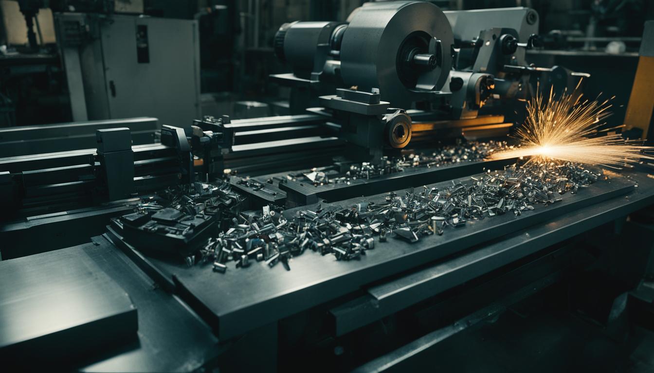
Computer Numerical Control (CNC) lathes represent a cornerstone of modern manufacturing, precisely shaping cylindrical components through automated processes. These sophisticated machines execute complex turning operations with exceptional accuracy and repeatability, driven by pre-programmed instructions. The integration of computer control significantly enhances productivity and part quality across diverse industries.
Unlike traditional manual lathes, CNC variants eliminate the need for continuous operator intervention, relying on G-code and M-code commands to dictate tool movements and machine functions. This automation minimizes human error, allowing for the consistent production of intricate geometries from various materials. The precision achieved makes CNC lathes indispensable for high-volume and high-accuracy part fabrication.
Computer-Controlled Turned Parts
CNC lathes excel at producing turned parts with precise dimensions and complex profiles, guided by digital design files. The machine’s control system interprets CAD/CAM data, translating it into specific toolpaths and operational parameters. This digital workflow ensures that each part is manufactured to exact specifications, critical for assembly and functional performance.
Modern CNC turning centers can create a wide array of components, including shafts, bushings, pins, and fittings. They are particularly efficient for parts requiring cylindrical, conical, or threaded features. The ability to maintain tight tolerances and achieve superior surface finishes makes these machines vital for aerospace, medical, and automotive sectors.
X and Z Linear Axis Motion
| Parameter | Typical Range / Standard | Notes |
|---|---|---|
| Standard Linear Tolerance | ±0.05 mm to ±0.13 mm | For most general metal parts. |
| High Precision Tolerance | ±0.025 mm or tighter | Requires specialized equipment and processes. |
| Standard Surface Finish (Ra) | 3.2 µm (125 µin) | ‘As-machined’ finish for general applications. |
| Fine Surface Finish (Ra) | 0.8 µm to 0.4 µm | For smooth surfaces, moving parts, enclosures. |
| Aluminum Cutting Speed (SFM) | 600 – 1200 | With carbide tooling for general alloys. |
| Steel Cutting Speed (SFM) | 100 – 300 | General guideline for various steel types. |
| Aluminum Roughing Feed Rate (IPR) | 0.004 – 0.010 | Inches per revolution, with carbide tooling. |
| Spindle Speed Range | 50 RPM to 4,500+ RPM | Depends on material, diameter, and operation. |
The fundamental motion system of a CNC lathe involves two primary linear axes: X and Z. The Z-axis controls the longitudinal movement of the cutting tool, parallel to the workpiece’s rotational axis, dictating the length of the turned feature. Conversely, the X-axis governs the radial movement, perpendicular to the Z-axis, determining the diameter of the workpiece.
Precision in these linear movements is achieved through high-quality ball screws and linear guides, driven by servo motors. Mid-range CNC lathes typically offer linear accuracy between ±0.01 mm and ±0.05 mm per 300 mm of travel, while high-end machines can achieve ±0.005 mm or better. This precise control is crucial for maintaining dimensional integrity across the entire part.
Automatic Tool Turret Indexing
Automatic tool turrets are integral to the efficiency of CNC lathes, housing multiple cutting tools and enabling rapid, automated tool changes. These turrets rotate, or ‘index,’ to bring the required tool into the machining position without manual intervention, significantly reducing setup times and increasing productivity.
Common turret interfaces include VDI (Verein Deutscher Ingenieure) and BMT (Base Mount Tooling), each offering distinct clamping mechanisms and toolholder compatibility. Many modern turrets feature ‘live tooling’ capabilities, where some stations are equipped with driven tools that can rotate independently. This transforms the lathe into a multi-functional machine, capable of milling, drilling, and tapping operations without transferring the workpiece to another machine.
Precision Thread Cutting
CNC lathes are highly adept at cutting precision threads, both external and internal, using specialized single-point threading tools. The machine’s control system synchronizes the spindle rotation with the linear feed rate of the cutting tool, ensuring an accurate thread pitch. This synchronization is critical for producing threads that meet specific engineering standards.
Programming for thread cutting often utilizes G-codes like G32 for single-pass threading or G76 for multi-pass threading cycles. The G76 cycle automates multiple passes, gradually reaching the final thread depth while maintaining consistent chip control. Best practices include using constant spindle speed (G97), applying multiple light passes for hard materials, and incorporating a ‘spring pass’ for high precision.
Cylindrical Stock Shaping
The primary function of a CNC lathe is to shape cylindrical stock by rotating the workpiece against a stationary cutting tool. This process, known as turning, removes material to achieve the desired external and internal geometries. The versatility of CNC lathes allows for a wide range of shaping operations beyond simple cylinders.
Operations include facing, which creates flat end surfaces; contour turning, which produces complex curved profiles; and taper turning, forming conical shapes. Grooving, chamfering, and cutting-off operations are also routinely performed. The machine’s ability to execute these diverse cuts with high precision makes it indispensable for manufacturing intricate components from raw bar stock.
Modern Engineering Practices and Performance
Achieving optimal performance in CNC turning relies on adherence to modern engineering practices, encompassing everything from material selection to post-process inspection. Standard CNC machining tolerances for most milling and turning operations typically range from ±0.05 mm to ±0.13 mm. For critical features, high-precision tolerances of ±0.025 mm or tighter are achievable with specialized equipment and controlled environments.
Material properties significantly influence achievable tolerances; for instance, aluminum alloys can achieve ±0.05 mm, while stainless steel typically holds ±0.10 mm. Surface finish is also a key consideration, with a standard ‘as-machined’ roughness often around Ra 3.2 µm. Smoother finishes, down to Ra 0.2 µm, are possible for applications requiring reduced friction or enhanced aesthetics.
Optimizing feeds and speeds is crucial for maximizing tool life, improving surface finish, and ensuring efficient material removal. For aluminum, cutting speeds often range from 600 to 1200 SFM with carbide tooling, and feed rates for roughing typically fall between 0.004 to 0.010 inches per revolution (IPR). Steel alloys generally require lower surface speeds, around 100 to 300 SFM.
Regular machine maintenance, including spindle concentricity checks and turret alignment, is paramount for sustaining accuracy. Advanced monitoring systems track tool wear and cutting forces, preventing defects and reducing scrap rates. Statistical Process Control (SPC) and Coordinate Measuring Machine (CMM) inspections ensure consistent part quality throughout production runs.