
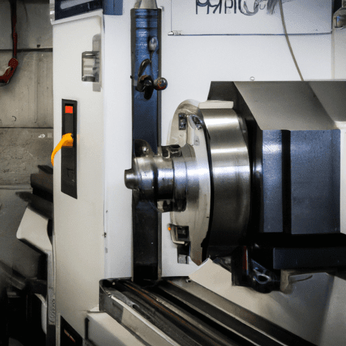
A Computer Numerical Control (CNC) lathe is a sophisticated machine tool designed for precision turning operations, automating the creation of cylindrical parts. It integrates advanced computer control with robust mechanical components to achieve high accuracy and repeatability in metalworking and other material processing.
These machines are fundamental in modern manufacturing, replacing traditional manual lathes due to their enhanced ease of setup, automation capabilities, and consistent precision. CNC lathes precisely shape materials by gradually shearing away excess material, resulting in highly accurate and intricately machined components.
The Computer-Controlled Turning Center
The core of a CNC lathe is its computer numerical control system, which interprets pre-programmed design instructions to automate machine tool movements. This digital control ensures unparalleled precision in governing spindle speed, tool movement, and workpiece positioning.
Programming a CNC lathe typically involves G-code and M-code. G-codes dictate specific movements, such as rapid traverses (G00) or linear interpolations (G01), while M-codes manage miscellaneous functions like coolant activation or spindle stop.
Modern CNC turning centers often feature multi-axis capabilities, allowing for concurrent movement along more than two axes. This versatility enables the production of intricate parts with complex geometries, significantly broadening the machine’s operational scope.
Advanced controls also facilitate ‘canned cycles’ (e.g., G70-G76 for turning, facing, grooving, and threading), which simplify complex machining sequences into single lines of code. This reduces programming time and minimizes potential errors.
Precision Spindle Dynamics
| Material | Cutting Speed (SFM) | Feed Rate (IPR) – Roughing | Feed Rate (IPR) – Finishing |
|---|---|---|---|
| 6061 Aluminum | 600-1200 | 0.004-0.010 | 0.002-0.005 |
| 304 Stainless Steel | 150-220 (m/min: 45-67) | 0.008-0.016 (mm/rev: 0.20-0.40) | 0.002-0.006 (mm/rev: 0.05-0.15) |
The spindle is the rotating element within the headstock of a CNC lathe, securely holding and rotating the workpiece during machining. Its motor allows for various speeds and drive mechanisms, accommodating a wide range of tasks.
Modern CNC lathe spindles can achieve high rotational speeds, with many production lathes operating between 3,000 and 4,000 RPM, and some high-speed models reaching 6,000 RPM or more.
Crucially, CNC lathes utilize ‘Constant Surface Speed’ (CSS) functionality, often activated by G96. This feature automatically adjusts the spindle’s RPM as the cutting tool moves across varying diameters of the workpiece, maintaining a consistent cutting speed at the tool tip.
Maintaining a consistent surface speed is vital for optimizing tool life, achieving desired surface finishes, and ensuring efficient chip formation. Without CSS, the surface speed would decrease as the tool approaches the workpiece center, leading to inconsistent cutting conditions.
Automated Tool Turret Systems
A critical component of a CNC lathe is its automated tool turret, designed to hold multiple cutting tools and facilitate rapid, programmed tool changes. This eliminates manual intervention, significantly enhancing efficiency and reducing downtime.
Tool turrets typically feature a disk-like or drum-like structure where various tools, such as turning, boring, and threading tools, are mounted. Smaller CNC lathes might have 4 or 8 tool stations, while larger machines can accommodate 12 or more.
The turret indexes automatically based on G-code commands (e.g., ‘T’ codes), rotating to position the correct tool for the next operation. Some turrets can rotate in both directions, optimizing for the nearest tool station to minimize changeover time.
Beyond standard turning tools, modern turrets can integrate ‘live tooling,’ which allows for secondary operations like milling, drilling, and tapping to be performed directly on the lathe without re-fixturing the part. This capability streamlines production and reduces cycle times.
X and Z Axis Motion Control
CNC lathes primarily operate with two linear axes: the X-axis, controlling radial movement (diameter), and the Z-axis, governing axial movement (length) along the workpiece. These axes enable the precise positioning and movement of the cutting tool relative to the rotating workpiece.
Movement along these axes is driven by highly accurate servo motors coupled with ball screws. Servo motors provide precise control over position, speed, and torque, utilizing closed-loop feedback systems with encoders to ensure micron-level accuracy.
Ball screws, often with accuracy grades like C3 or C5 for CNC machines, translate the rotational motion of the servo motors into precise linear motion. The accuracy grade indicates the permissible lead error over a specified travel distance, with lower numbers signifying higher precision.
Axis acceleration and deceleration are also critical for efficiency, with typical CNC lathes achieving accelerations around 0.2g (2 m/s²), while high-speed machines can reach up to 2g (20 m/s²). This affects rapid traverse times, especially for smaller parts.
Mastering Cylindrical Machining
Cylindrical machining, or turning, is the fundamental operation of a CNC lathe, where material is removed from a rotating workpiece to create a desired cylindrical shape. This encompasses a variety of operations, including facing, turning outer diameters (OD), boring inner diameters (ID), grooving, and threading.
Achieving high precision in these operations relies on carefully calculated feeds and speeds. ‘Cutting speed’ (SFM or m/min) refers to the speed at which the workpiece surface passes the cutting tool, while ‘feed rate’ (IPM or mm/min, or IPR/mm/rev) is the distance the tool travels per revolution or per minute.
Standard tolerances for CNC lathe operations typically range from ±0.005 inches (±0.127 mm) for general-purpose parts. However, high-precision machines can achieve much tighter tolerances, down to ±0.0001 inches (±0.0025 mm) for critical applications like aerospace or medical components.
Here are typical feeds and speeds for common materials using carbide tooling:
These parameters are starting points and must be adjusted based on specific tooling, machine rigidity, depth of cut, and desired surface finish. Proper coolant application is also crucial to prevent chip welding and extend tool life, especially with materials like aluminum.