
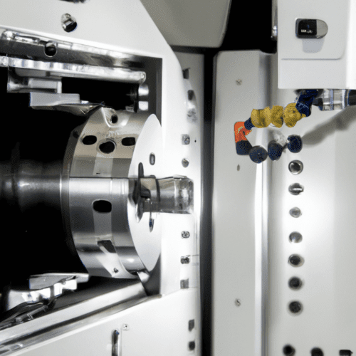
Computer Numerical Control (CNC) machines represent a fundamental shift in manufacturing, automating the precise control of machine tools through pre-programmed computer software. These systems transform digital designs into physical components with exceptional accuracy and repeatability, surpassing the capabilities of manual machining.
CNC technology is an evolution of earlier numerical control (NC) systems, which relied on data storage media like punched cards. The advent of affordable computing allowed for easier programming, real-time adjustments, and greater flexibility, leading to the widespread adoption of CNC across various industries.
Subtractive Manufacturing Principle
Subtractive manufacturing is a process where material is removed from a solid block, often called a ‘blank’ or ‘workpiece,’ to achieve a desired 3D geometrical shape. This contrasts with additive manufacturing, which builds parts layer by layer.
CNC machining is a primary method of subtractive manufacturing, utilizing computer-controlled tools to cut, drill, mill, or turn materials. Common techniques include milling, where rotating cutting tools remove material, and turning, where the workpiece rotates against a stationary tool.
This material removal process is critical for industries demanding high precision and durability, such as aerospace, automotive, and medical device manufacturing. Subtractive methods generally offer superior accuracy and smoother surface finishes, especially for parts requiring tight tolerances.
Computer Controller Functionality
| Material | Cutting Speed (SFM) | Feed per Tooth (IPT) | Notes |
|---|---|---|---|
| 6061 Aluminum | 800 – 1500+ | 0.002 – 0.010 | High helix angles, polished flutes, flood coolant recommended. |
| 304 Stainless Steel | 150 – 250 | 0.001 – 0.006 | Lower chip load, higher surface speed for work-hardening materials. |
The CNC controller acts as the ‘brain’ of the machine, interpreting digital instructions and translating them into precise mechanical movements. It manages various machine functions, including axis movement, spindle speed, and tool changes.
Modern CNC controllers typically feature a central processing unit (CPU), memory for program storage, and input/output (I/O) interfaces to communicate with machine components. Popular controller brands include Fanuc, Siemens, and Haas, each offering distinct programming and operational characteristics.
These controllers rely on feedback systems, often employing encoders, to monitor the exact position of each axis. This closed-loop feedback ensures that the actual tool position precisely matches the programmed coordinates, maintaining high accuracy throughout the machining process.
G-Code Instruction Execution
G-code, or ‘Geometric Code,’ is the fundamental programming language that instructs CNC machines on how to move and operate. It defines the tool’s path, speed, and position in a sequential program of machine control instructions.
M-codes, or ‘Miscellaneous Codes,’ complement G-codes by controlling non-geometric machine functions. These include actions like starting or stopping the spindle, activating coolant, and initiating tool changes.
Computer-Aided Manufacturing (CAM) software plays a crucial role in generating G-code. Engineers design parts using Computer-Aided Design (CAD) software, and then CAM software translates these 3D models into the specific toolpaths and G-code instructions required for machining.
The execution flow begins with loading the G-code program into the CNC controller. The controller then interprets each line of code, driving the machine’s motors and actuators to perform the specified cutting operations.
Here is a list of common G-codes and M-codes:
- Common G-Codes:
- G00: Rapid positioning (non-cutting movement)
- G01: Linear interpolation (straight line cutting at a controlled feed rate)
- G02: Circular interpolation clockwise (arc movement)
- G03: Circular interpolation counter-clockwise (arc movement)
- G04: Dwell (pause for a specified time)
- G90: Absolute programming (coordinates from origin)
- G91: Incremental programming (coordinates relative to current position)
- G20/G21: Inch/Metric unit selection
- Common M-Codes:
- M00: Program stop
- M03: Spindle on (clockwise rotation)
- M05: Spindle stop
- M06: Tool change
- M08: Coolant on
- M09: Coolant off
- M30: Program end and reset
Automatic Cutting Motion
CNC machines achieve automatic cutting motion through precisely controlled multi-axis systems. A 3-axis machine moves along the X, Y, and Z linear axes, while 4-axis and 5-axis machines add rotational capabilities, allowing the tool to approach the workpiece from more complex angles.
Motion is typically driven by stepper or servo motors, which receive commands from the CNC controller. Servo motors, often preferred for industrial applications, provide higher precision and feedback, ensuring accurate positioning and dynamic response.
Linear motion is converted from rotary motor motion using ball screws, which are highly accurate mechanisms with reduced friction compared to traditional lead screws. Ball screws minimize backlash, ensuring precise and smooth movement of the machine’s axes.
Tool path generation, a core function of CAM software, defines the exact route the cutting tool will take. This includes linear interpolation for straight cuts and circular interpolation for arcs, all calculated to remove material efficiently and accurately.
Quality Production Workflow
A robust quality production workflow in CNC machining integrates several critical stages, beginning with seamless CAD/CAM integration. This ensures that the digital design intent is accurately translated into machine instructions, minimizing errors from the outset.
Tooling selection is paramount, involving choosing the correct cutting tools, tool holders, and inserts for the specific material and operation. Proper tool geometry, material (e.g., carbide), and coatings significantly impact surface finish, tool life, and material removal rates. For instance, uncoated or polished carbide tools with high helix angles are often recommended for aluminum.
Workholding strategies are essential for securing the workpiece rigidly, preventing movement or vibration during machining. Effective fixturing ensures consistent part accuracy and surface quality, especially when dealing with complex geometries or aggressive cutting parameters.
Optimizing feeds and speeds—the spindle speed (RPM) and the rate at which the tool advances through the material (IPM/mm/min)—is crucial for efficiency, tool life, and surface finish. Incorrect settings can lead to premature tool wear, poor surface quality, or even part damage.
Metrology and inspection are integrated throughout the process, not just at the end. On-machine probing systems verify workpiece setup, monitor machined features, and detect tool inconsistencies in real-time, reducing scrap and rework. Coordinate Measuring Machines (CMMs) provide precise, automated dimensional inspection for complex geometries and tight tolerances, often integrated directly into machining cells for in-process verification.
Standard tolerances, such as those defined by ISO 2768-1 for general tolerances or ASME Y14.5 for geometric dimensioning and tolerancing (GD&T), guide the acceptable deviation from nominal dimensions. Adherence to these standards ensures parts meet functional requirements and maintain interchangeability.