
Computer Numerical Control (CNC) machining forms the bedrock of modern manufacturing, enabling the production of intricate and precise components across diverse industries. Within this expansive field, CNC lathes and CNC milling machines represent two fundamental, yet distinct, subtractive manufacturing technologies. While both utilize pre-programmed digital instructions to remove material from a workpiece, their operational kinematics, part geometries, and tooling approaches diverge significantly.
Understanding these core differences is paramount for engineers and machinists to select the optimal process for a given part, ensuring efficiency, accuracy, and cost-effectiveness. The choice between turning and milling directly impacts everything from surface finish quality to overall production capabilities.
Fundamental Kinematics: Workpiece and Tool Motion
The most fundamental distinction between a CNC lathe and a CNC milling machine lies in their primary motion. A CNC lathe, often referred to as a turning center, operates by rotating the workpiece at high speeds against a stationary, single-point cutting tool.
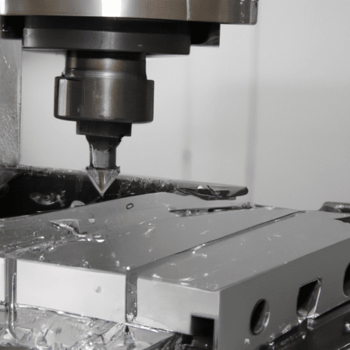
Conversely, a CNC milling machine holds the workpiece stationary while a multi-point, rotating cutting tool, such as an end mill or face mill, moves along various axes to remove material. This reversal of rotational responsibility defines the core mechanical action of each machine.
On a lathe, the workpiece is typically secured in a chuck or collet, rotating around its own axis. The cutting tool then approaches the spinning material, performing operations like facing, boring, grooving, and threading. This setup is inherently optimized for creating parts with rotational symmetry.
Milling machines, however, fix the workpiece to a machine bed or fixture. The spindle, housing the cutting tool, then rotates at high RPMs, and the tool itself translates across the workpiece to sculpt complex shapes, flat surfaces, slots, and holes.
Axis Configuration and Machining Complexity
| Feature | CNC Lathe (Turning) | CNC Milling Machine (Milling) |
|---|---|---|
| Workpiece Motion | Rotates | Stationary (or moves along axes) |
| Tool Motion | Stationary (moves linearly) | Rotates (moves linearly and/or rotationally) |
| Primary Part Geometry | Cylindrical, conical, spherical | Flat, prismatic, complex 3D shapes |
| Typical Axes | 2-axis (X, Z), multi-axis with C, Y, B | 3-axis (X, Y, Z), 4-axis, 5-axis |
| Tool Type | Single-point cutting tools | Multi-point cutting tools (end mills, face mills) |
| Standard Tolerance (Metal) | ±0.005″ (±0.127 mm) | ±0.005″ (±0.127 mm) |
| Tight Tolerance (Metal) | ±0.001″ (±0.025 mm) | ±0.001″ (±0.025 mm) |
CNC machines are defined by their axis count, which dictates the complexity of parts they can produce. A standard 2-axis CNC lathe primarily operates along the X and Z axes. The Z-axis controls longitudinal movement along the spindle centerline, while the X-axis controls radial movement, determining the diameter of the part.
Multi-axis turning centers can incorporate additional axes, such as a C-axis for controlled spindle rotation, allowing for contouring and the machining of complex features like cams or grooves. Some advanced lathes also feature Y-axis movement or a B-axis tilting milling spindle, enabling milling and drilling operations on turned parts without secondary setups.
CNC milling machines typically start with a 3-axis configuration (X, Y, Z). The X-axis handles left-to-right movement, Y-axis front-to-back, and Z-axis up-and-down, allowing for material removal across three dimensions. This setup is suitable for machining simple parts with basic features.
More sophisticated milling machines, such as 4-axis and 5-axis models, introduce rotary axes (A, B, C) that allow the tool or workpiece to rotate, enabling machining from multiple angles in a single setup. This capability is crucial for intricate surfaces, undercuts, and complex 3D geometries often found in aerospace or medical components.
Part Geometry and Application Focus
The inherent kinematics of each machine type naturally lend themselves to specific part geometries. CNC lathes are ideally suited for producing cylindrical, conical, or spherical parts. Common applications include shafts, pins, bushings, screws, and other components requiring rotational symmetry.
Milling machines, conversely, excel at creating parts with flat surfaces, irregular shapes, and intricate features. They are the go-to choice for prismatic parts, housings, brackets, molds, and components with pockets, slots, and grooves.
While modern turn-mill machines blur these lines by combining capabilities, the core strength of a lathe remains its efficiency in generating precise round features, while a mill’s strength lies in its versatility for complex, non-rotationally symmetric forms.
Tooling and Spindle Dynamics
Tooling on a CNC lathe typically consists of single-point cutting tools mounted in a tool turret. These tools are stationary relative to the machine’s linear axes during the cut, with the workpiece’s rotation providing the necessary cutting speed.
Milling machines utilize multi-point cutting tools, such as end mills, ball nose mills, and face mills, which are held in a spinning spindle. The spindle itself is a critical component, providing the high-speed rotation for the cutting tool. Modern spindles offer precise RPM control and are designed for continuous, heavy-duty operation.
The choice between a router and a spindle for milling applications depends on the required precision and duty cycle. Spindles, often paired with Variable Frequency Drives (VFDs), offer superior rigidity, precise RPM control, and longer continuous operation compared to less robust trim routers.
Process Terminology: Turning versus Milling
The operations performed on these machines also have distinct terminology. ‘Turning’ encompasses processes like facing (machining the end of a part), boring (enlarging an existing hole), grooving (cutting a channel), and threading (creating screw threads).
Milling’ involves operations such as face milling (creating flat surfaces), end milling (cutting slots, pockets, and profiles), drilling (creating holes), and contouring (machining complex 3D shapes). These terms reflect the fundamental difference in how material is removed and the resulting geometry.
Precision, Tolerances, and Modern Practices
Both CNC turning and milling machines are capable of achieving high precision. Standard CNC machining tolerances for most metals typically range from ±0.005 inches (±0.127 mm). For applications demanding greater accuracy, such as aerospace or medical components, tolerances as tight as ±0.001 inches (±0.025 mm) or even ±0.0001 inches (±0.0025 mm) can be achieved with specialized machines and processes.
Achieving tighter tolerances often necessitates additional machining passes, more frequent dimensional checks, and can increase costs due to extended cycle times and potential scrap. Material choice significantly impacts achievable tolerances; softer materials like aluminum generally machine to tighter tolerances more easily than harder materials such as stainless steel.
Modern engineering practices in 2026 emphasize smart manufacturing, integrating AI-driven control systems, predictive maintenance, and digital twin technologies. These advancements optimize feeds and speeds in real-time, reduce tool wear, and improve overall process stability and part quality.
Feeds and speeds are critical parameters for both turning and milling, directly impacting tool life, surface finish, and material removal rates. For aluminum milling, typical spindle speeds range from 8,000–12,000 RPM with feed rates of 40–80 IPM, using a 2-flute end mill with a chip load of 0.001–0.003 inch. For turning steel, roughing operations might use a feed of 0.25–0.5 mm/rev, while finishing operations require a lower feed of 0.05–0.15 mm/rev for superior surface finish.
Here is a comparison of key technical parameters: