
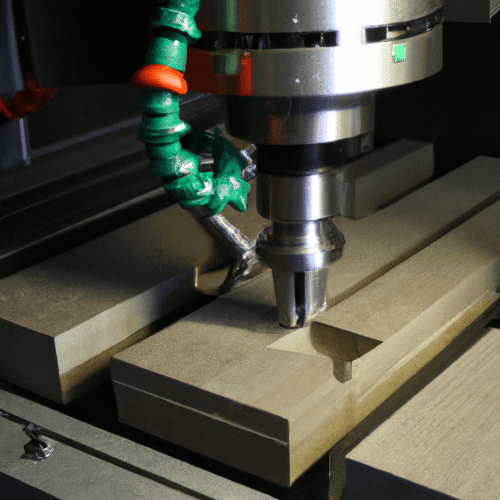
Computer Numerical Control (CNC) milling machines represent a cornerstone of modern manufacturing, enabling the precise removal of material from a workpiece through automated, multi-axis motion. These sophisticated systems translate digital designs into physical components with exceptional accuracy and repeatability.
The fundamental principle involves a rotating cutting tool engaging a stationary or moving workpiece, guided by a computer program. This process allows for the creation of complex geometries and tight tolerances across a vast array of materials, from soft plastics to hardened alloys.
Understanding CNC Milling Machine Axes
CNC milling machines are categorized by the number of axes along which their cutting tool or workpiece can move simultaneously, directly influencing their capabilities and the complexity of parts they can produce. A 3-axis mill operates along the X (left-right), Y (front-back), and Z (up-down) axes, suitable for most prismatic parts and general machining operations.
Adding a fourth axis, typically a rotary axis (A or B) that rotates the workpiece or the cutting head, significantly expands machining possibilities. This 4-axis configuration allows for continuous contouring on cylindrical or irregular surfaces, reducing the need for multiple setups and improving part accuracy.
The most advanced machines are 5-axis mills, which incorporate two rotary axes in addition to the three linear axes. This enables the cutting tool to approach the workpiece from virtually any angle, facilitating the machining of highly complex, organic shapes, undercuts, and impellers in a single setup.
Five-axis machining minimizes fixture requirements and tool changes, leading to superior surface finishes and tighter tolerances on intricate components. This capability is particularly critical in aerospace, medical, and mold-making industries where part complexity is paramount.
The Heart of the Operation: Spindle and Tooling
| Material | Tool Material | Spindle Speed (RPM) | Feed Rate (mm/min) | Depth of Cut (mm) | Surface Finish (Ra µm) |
|---|---|---|---|---|---|
| Aluminum 6061 | Carbide (2-flute) | 8,000 – 15,000 | 1,500 – 3,000 | 0.5 – 2.0 | 0.4 – 1.6 |
| Stainless Steel 304 | Carbide (4-flute) | 2,000 – 5,000 | 300 – 800 | 0.2 – 1.0 | 0.8 – 3.2 |
| Titanium Grade 5 | Carbide (5-flute) | 1,000 – 3,000 | 150 – 400 | 0.1 – 0.5 | 0.8 – 3.2 |
| Delrin (POM) | HSS (2-flute) | 5,000 – 10,000 | 1,000 – 2,500 | 1.0 – 3.0 | 0.2 – 0.8 |
The spindle cutting assembly is the core component responsible for holding and rotating the cutting tool at high speeds, directly impacting machining performance and surface finish. Spindles vary significantly in power, speed, and torque, tailored to specific machining applications and materials.
High-speed spindles, often reaching 20,000 to 80,000 RPM, are essential for machining softer materials, small-diameter tools, and achieving fine surface finishes. Conversely, high-torque spindles operating at lower RPMs are preferred for heavy material removal in harder metals.
Tool holding systems ensure the cutting tool is rigidly secured and precisely centered within the spindle. Common systems include CAT, BT, HSK, and Capto interfaces, each offering different levels of rigidity, runout accuracy, and tool change speed. HSK (Hollow Shank Taper) systems, for instance, provide excellent radial and axial rigidity, crucial for high-speed and heavy-duty machining.
Cutting tools themselves are engineered from various materials like high-speed steel (HSS), carbide, ceramics, and superhard materials like polycrystalline diamond (PCD) or cubic boron nitride (CBN). The choice depends on the workpiece material, desired surface finish, and tool life requirements. Modern end mills often feature advanced coatings, such as TiAlN or AlCrN, to enhance hardness, lubricity, and heat resistance.
Precision Motion Control: Closed-Loop Servo Systems
Closed-loop servo motors are indispensable for the high precision and dynamic performance of modern CNC milling machines. Unlike open-loop stepper motors, servo systems continuously monitor their actual position and velocity, comparing it to the commanded position and making real-time adjustments.
Each axis of a CNC machine is driven by a servo motor coupled with a ball screw, which translates rotary motion into precise linear movement. An encoder, typically optical or magnetic, provides feedback on the motor’s exact position to the servo drive, forming the ‘closed loop’.
This continuous feedback mechanism allows servo systems to maintain extremely tight positional accuracy and repeatability, even under varying load conditions. They can accelerate and decelerate rapidly, enabling faster traverse rates and more efficient machining cycles compared to stepper motor systems.
The dynamic response and high resolution of closed-loop servos are critical for achieving the intricate contours and fine details demanded by complex part geometries. They virtually eliminate lost steps, ensuring that the machine’s actual position precisely matches the programmed path.
The Brain: Machine Control Unit (MCU)
The Machine Control Unit (MCU) serves as the central processing unit of a CNC milling machine, interpreting the programmed instructions and translating them into precise machine movements. It comprises a computer, a human-machine interface (HMI), and specialized hardware for motion control.
The MCU reads G-code (geometric code) and M-code (miscellaneous code) programs, which define tool paths, feed rates, spindle speeds, and auxiliary functions like coolant activation or tool changes. Advanced MCUs feature powerful processors capable of look-ahead functions, optimizing tool paths for smoother motion and faster machining.
Modern MCUs offer sophisticated features such as real-time tool path simulation, collision detection, adaptive control, and network connectivity for integration into factory automation systems. They also support various programming methods, including conversational programming and direct CAD/CAM integration.
The reliability and processing speed of the MCU are paramount for consistent part quality and efficient operation. Leading manufacturers like Fanuc, Siemens, and Heidenhain develop MCUs known for their robust performance and extensive feature sets, catering to diverse industrial requirements.
Achieving Excellence: Precision Metal Removal
Precision metal removal in CNC milling is a multifaceted discipline, relying on a synergistic combination of machine rigidity, cutting tool selection, programming strategies, and process control. Achieving tight dimensional tolerances and superior surface finishes requires meticulous attention to detail at every stage.
Factors influencing precision include machine vibration, thermal expansion, tool deflection, and workpiece clamping. Modern machines incorporate features like thermal compensation, high-resolution linear scales, and robust machine structures to mitigate these effects.
Surface finish, often measured in Ra (arithmetic average roughness), is critical for part functionality and aesthetics. Achieving low Ra values typically involves using sharp, specialized finishing tools, higher spindle speeds, lower feed rates, and optimized coolant strategies.
Standard tolerances for CNC machining vary widely based on material, machine capability, and part requirements. For general machining, ISO 2768-1 ‘f’ (fine) or ‘m’ (medium) tolerances are often applied, allowing for deviations in the range of ±0.05 mm to ±0.5 mm depending on the dimension. Precision applications, however, frequently demand tolerances as tight as ±0.005 mm or even finer.
These parameters are general guidelines and must be optimized for specific tooling, machine rigidity, and desired outcomes. Advanced CAM software plays a crucial role in generating efficient tool paths and optimizing feeds and speeds to achieve the required precision and surface quality.