
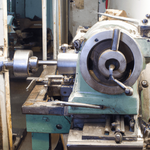
A conventional lathe, often termed a manual or engine lathe, remains a foundational machine tool in manufacturing, essential for shaping and modifying various materials with precision. This versatile equipment operates by rotating a workpiece against a stationary cutting tool, allowing operators to manually control material removal and achieve desired forms. Its enduring relevance stems from its flexibility and direct operator control, particularly for unique or small-batch production runs.
Unlike its Computer Numerical Control (CNC) counterparts, a conventional lathe relies heavily on the machinist’s skill and direct physical interaction. This hands-on approach provides immediate feedback and adaptability, making it invaluable for prototyping, repairs, and custom component fabrication. Understanding its core mechanical systems is crucial for any tooling engineer or machinist.
Manual Control and Operator Interaction
Direct manual control is a defining characteristic of conventional lathes, where machinists manipulate handwheels to precisely position the cutting tool. The longitudinal handwheel moves the carriage along the lathe bed, controlling movement along the Z-axis. This allows for axial cuts, such as turning down a shaft’s length.
The cross-slide handwheel, mounted on the carriage, facilitates radial movement of the tool, often referred to as the X-axis. Turning this handwheel adjusts the cutting depth and workpiece diameter. Graduated dials on these handwheels provide incremental measurements, typically in thousandths of an inch or hundredths of a millimeter, enabling fine adjustments for precise material removal.
For threading operations, the half-nut lever engages the lead screw, synchronizing the carriage movement with the spindle’s rotation. This mechanical linkage ensures consistent thread pitch. Operators must carefully manage backlash in the lead screw and handwheel mechanisms to maintain accuracy, especially during critical finishing passes.
Power Transmission and Speed Management
| Parameter | Typical Range (General Purpose) | Notes |
|---|---|---|
| Spindle Speed Range | 40 – 2500 RPM | Varies significantly with gearbox design and motor power. |
| Longitudinal Feed Rate (Roughing) | 0.005 – 0.020 inches/revolution | Higher rates for faster material removal. |
| Longitudinal Feed Rate (Finishing) | 0.002 – 0.004 inches/revolution | Lower rates for better surface finish and dimensional accuracy. |
| Standard Machining Tolerance | ±0.002″ to ±0.005″ (±0.05 mm to ±0.1 mm) | Achievable with competent operator and well-maintained machine. |
| Surface Finish (Roughing) | Rα 20 – 10 μm | Dependent on feed, speed, and tool geometry. |
| Surface Finish (Finishing) | Rα 10 – 0.16 μm | Achievable with fine feeds and sharp tools. |
Conventional lathes utilize robust power transmission systems to deliver rotational force to the workpiece. Belt drive mechanics are common, where a motor drives the spindle via a series of belts and pulleys. This system offers advantages such as vibration damping, which contributes to a smoother surface finish, and cost-effectiveness.
Speed selection on a conventional lathe is primarily managed through a gearbox, often located within the headstock. This gearbox contains sliding gear clusters and shift levers that allow the operator to select various spindle speeds. Older designs might use step cone pulleys, requiring manual belt repositioning to change speeds, while more modern conventional lathes feature geared headstocks for quicker, more repeatable speed changes.
The gearbox provides a range of discrete RPMs, often with a ‘back gear’ mechanism to achieve very low speeds with high torque, suitable for heavy roughing cuts on large diameter workpieces. A typical engineering lathe might offer 8 to 12 distinct speeds, covering a range from 40 RPM for heavy cuts to over 2500 RPM for fine finishing of smaller parts. This mechanical advantage is crucial for matching cutting conditions to material and tool requirements.
Operator Manual Feed and Precision
Beyond direct handwheel control, conventional lathes incorporate an operator manual feed system for consistent material removal. The feed rod, driven by the headstock’s gearing, transmits power to the apron, which then engages either the carriage for longitudinal feed or the cross-slide for transverse feed. A power feed clutch allows the operator to engage or disengage this automatic movement.
Selecting the appropriate feed rate is critical for achieving desired surface finishes and efficient material removal. For roughing operations, a coarser feed rate, typically between 0.005 and 0.020 inches per revolution, is employed to remove material quickly. Finishing cuts demand a finer feed, generally ranging from 0.002 to 0.004 inches per revolution, to produce a smooth surface and achieve final dimensions.
Achieving tight tolerances on a conventional lathe is a testament to operator skill and machine condition. Standard machining on manual lathes commonly holds tolerances from ±0.002″ to ±0.005″ (±0.05 mm to ±0.1 mm). Highly skilled machinists, however, can achieve tighter tolerances, sometimes reaching ±0.0005″ (±0.01 mm) or better for critical applications, though this requires meticulous attention and experience.
Feeds, Speeds, and Modern Practices
Determining optimal feeds and speeds is fundamental to successful turning operations on a conventional lathe. Surface Feet per Minute (SFM) is a key parameter, representing the tangential speed at which the cutting tool engages the workpiece. For mild steel with High-Speed Steel (HSS) tooling, recommended SFM values are typically around 60-100, while carbide tooling can allow for significantly higher SFM, often 150-180.
The spindle Revolutions Per Minute (RPM) is calculated using the SFM and the workpiece diameter. For example, turning a 1-inch diameter mild steel workpiece with an HSS tool at 100 SFM would require approximately 400 RPM. These values are guidelines, and machinists often adjust them based on factors like workpiece rigidity, machine condition, and desired surface finish.
Modern engineering practices, even with conventional lathes, emphasize tool material selection and cutting fluid application. While HSS tools are common, carbide inserts offer superior hardness and heat resistance, enabling higher cutting speeds and longer tool life. Proper lubrication is also crucial, as it reduces friction, dissipates heat, and improves chip evacuation, all contributing to better surface finish and tool longevity.
The Enduring Role of Non-CNC Turning
Despite the prevalence of CNC technology, non-CNC turning continues to hold a vital place in various industries. Conventional lathes are particularly well-suited for one-off parts, prototypes, and repair work where the setup time for CNC programming would be prohibitive. Their ability to begin work immediately without complex programming offers a significant advantage for urgent or non-standard jobs.
The lower initial investment and maintenance costs associated with conventional lathes make them an economical choice for small workshops, educational institutions, and toolrooms. They foster a deep understanding of machining principles and craftsmanship, as operators gain hands-on experience with every aspect of the cutting process. This direct engagement with the machine cultivates a unique skill set.
Conventional lathes also serve as excellent complements to CNC machinery in many facilities. They can handle quick, simple tasks, freeing up CNC machines for complex, high-volume production runs. This symbiotic relationship ensures that both traditional craftsmanship and advanced automation contribute to overall manufacturing efficiency.