
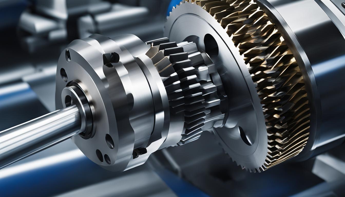
The CNC spindle serves as the fundamental component responsible for rotating the cutting tool at precise speeds and delivering the necessary power for material removal. This motor-driven tool assembly is the heart of any CNC machine, directly influencing machining accuracy, surface finish, and overall productivity. Its design integrates various advanced technologies to meet the rigorous demands of modern manufacturing processes.
Spindles are engineered to hold cutting tools securely, ensuring stability even at extremely high rotational speeds. They are seamlessly integrated with the machine’s control system, allowing for dynamic adjustments to speed and torque based on the material being processed and the desired machining operation. This intricate coordination is vital for achieving optimal cutting performance.
Understanding the CNC Spindle Assembly
A CNC spindle is far more than just a rotating shaft; it is a sophisticated assembly comprising a motor, high-precision bearings, and a tool interface. These components work in concert to provide the rotational force and stability required for diverse machining tasks, from delicate engraving to heavy material removal. Modern spindles often incorporate advanced cooling systems and sensors for real-time monitoring.
The motor within the spindle assembly is typically an AC induction or brushless DC motor, chosen for its ability to achieve high speeds and torque while maintaining accuracy. Precision bearings, often angular contact ball bearings, support the rotor and ensure minimal vibration and deflection during operation. The tool interface, or taper, provides a standardized and repeatable method for attaching cutting tools.
Recent advancements in spindle technology include integrated motor designs, where the motor rotor is directly incorporated into the spindle shaft, eliminating belts and gears. This design reduces mechanical losses, enables faster acceleration and deceleration, and allows for higher rotational speeds. Smart spindles, equipped with embedded sensors, can monitor temperature, vibration, and load, facilitating predictive maintenance and enhancing operational efficiency.
Tool Holding Systems: BT, CAT, and HSK Tapers
| Feature | CAT Taper | BT Taper | HSK Taper |
|---|---|---|---|
| Origin | North America (US) | Asia (Japan) | Europe (Germany) |
| Taper Ratio | 7:24 | 7:24 | 1:10 |
| Contact Type | Taper only | Taper only | Taper and Face (Dual Contact) |
| Clamping Mechanism | External pull stud | External pull stud | Internal expanding clamps |
| Rigidity | Good | Good (balanced) | Excellent (5-7x higher than BT/SK) |
| High RPM Performance | Limited (loss of preload) | Limited (loss of preload) | Superior (maintains/increases grip) |
The interface between the cutting tool and the spindle is critical for maintaining rigidity and accuracy during machining. Three prominent tool holding systems dominate the CNC industry: BT, CAT, and HSK tapers. Each system offers distinct characteristics influencing performance, particularly at varying spindle speeds and cutting loads.
CAT (Caterpillar) tool holders, prevalent in North America, utilize a 7:24 taper ratio and are known as V-flange holders. They rely on taper contact with the spindle and are secured by an external pull stud. While widely used, CAT holders can experience a reduction in grip at higher RPMs due to centrifugal expansion of the spindle bore, potentially leading to ‘Z-axis creep’.
BT (Bottle Taper) tool holders, common in Asia, also feature a 7:24 taper ratio but are symmetrical about the spindle axis, offering good balance. Like CAT, they primarily use taper contact and an external pull stud. The flange configurations of CAT and BT tools are different, making them non-interchangeable.
HSK (Hollow Shank Taper) tool holders, originating from Europe, represent a significant advancement, especially for high-speed machining. They feature a shallower 1:10 taper and a hollow shank design that allows for simultaneous face and taper contact with the spindle. This dual-contact mechanism provides superior rigidity and dynamic balance, with clamping forces up to twice that of BT and CAT holders. HSK holders maintain or even increase their interference fit as spindle speed rises, counteracting centrifugal expansion.
High RPM Spindle Power and Performance
Spindle rotational speed, measured in Revolutions Per Minute (RPM), is a critical performance parameter, especially for modern machining applications. High RPMs are essential for achieving optimal surface finishes, particularly with small diameter tools, and for efficiently machining softer materials like aluminum, plastics, and composites.
Spindle power, typically expressed in kilowatts (kW) or horsepower (HP), directly correlates with the torque available for cutting and the material removal rate. Higher power spindles are necessary for heavy-duty cutting, deep hole drilling, and processing hard materials such as steel and stainless steel. For instance, cutting aluminum with a 1-inch, 4-flute cutter at 30,000 RPM might require a spindle delivering around 60 HP.
Modern CNC spindle motors, including AC induction and brushless DC types, are designed to achieve speeds up to 20,000 RPM, with high-frequency spindles often exceeding this for intricate work. These motors, often integrated directly into the spindle assembly, provide a flat torque profile across a wide speed range, crucial for versatile machining. The choice of spindle power and speed must align with the specific materials, tool sizes, and cutting intensity of the intended applications.
Spindle Cooling Methods: Air vs. Liquid
Effective heat management is paramount for maintaining spindle performance, accuracy, and longevity. Spindles generate significant heat from motor operation and bearing friction, especially during prolonged high-speed use. Inadequate cooling can lead to thermal expansion, reduced precision, premature bearing wear, and even spindle failure.
Air-cooled spindles utilize integrated fans, either shaft-driven or electric, to circulate ambient air around the motor housing and dissipate heat. These systems are generally simpler in design, more cost-effective, and require less maintenance, making them suitable for lighter workloads and smaller setups. However, air cooling is less efficient for high-power, high-speed, or continuous-duty applications and can be noisier.
Liquid-cooled spindles employ a closed-loop system that circulates water or a specialized coolant through the spindle’s internal channels. This coolant absorbs heat and is then pumped to an external radiator or chiller for dissipation. Liquid cooling offers superior heat removal, precise temperature control, and consistent performance, making it ideal for demanding, high-speed, and high-power industrial applications. While more complex and costly upfront, liquid-cooled systems typically result in quieter operation and extended spindle lifespan due to reduced thermal stress.
Achieving Precision: Spindle Runout Accuracy
Spindle runout is a critical metric defining the precision of a CNC machine, referring to the deviation of the tool’s rotational axis from its true geometric axis. This deviation can manifest as radial runout (perpendicular to the axis) or axial runout (along the axis). Even minute runout significantly impacts machining quality, tool life, and part accuracy.
Excessive runout leads to uneven cutting forces, accelerated tool wear, poor surface finishes, and inaccurate part dimensions, potentially resulting in rejected parts. For general machining, acceptable spindle runout should be less than 0.02 mm. However, for high-precision CNC tasks, the requirement tightens considerably, demanding runout below 0.005 mm (5 microns) or even 0.0002 inches (approximately 5 microns) for high-speed HSK spindles.
Factors influencing spindle runout include the quality of the spindle bearings, the precision of the assembly, and the accuracy of the tool holder itself. Precision CNC machining centers often specify radial runout tolerances between 5-10 micrometers (0.0002-0.0004 inches) for precision VMCs, with high-speed HSK spindles aiming for 2-5 micrometers (0.00008 inches). Regular measurement using a dial test indicator and a spindle test bar is essential to verify and maintain these critical tolerances.