
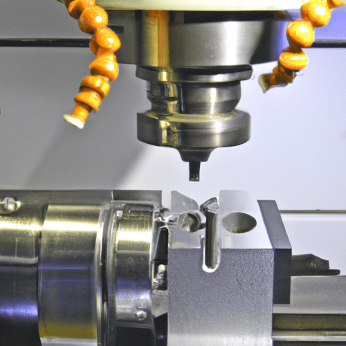
Computer Numerical Control (CNC) machining represents a foundational technology in modern manufacturing, enabling the precise creation of complex components. This automated process relies on computer software to direct machine tools, removing material from a workpiece to achieve a desired shape. It stands as a cornerstone for industries requiring high accuracy and repeatability, from aerospace to medical devices.
The core principle involves transforming raw material, such as metal or plastic, into a finished part by systematically cutting away excess material. This method ensures exceptional surface finishes and structural integrity, making it indispensable for industrial-grade components.
Subtractive Computer Manufacturing Fundamentals
Subtractive manufacturing is defined by the removal of material from a solid block, often called a blank or workpiece, to form a final shape. This contrasts sharply with additive manufacturing, which builds objects layer by layer. While 3D printing (additive) excels at intricate or internal geometries for one-off parts, subtractive methods generally offer superior accuracy and smoother surface finishes for traditional part shapes, especially when tight tolerances are critical.
Engineers utilize various subtractive techniques, including milling, turning, drilling, grinding, and laser cutting. Each technique employs a distinct method of material removal, such as rotating cutters in milling or concentrated light beams in laser cutting. The overarching goal remains the careful subtraction of material to precisely match the final design.
Modern CNC systems automate these processes, ensuring high precision, consistency, and efficiency. This automation is crucial for transforming raw materials into finished parts by cutting away excess material in precise sections.
Automated Cutting Processes and Machine Types
| Material | Tool Type | Typical SFM (Carbide) | Typical Chip Load (in/tooth) | Notes |
|---|---|---|---|---|
| Aluminum 6061 | Carbide End Mill | 800-1000 | 0.003-0.008 (depending on diameter) | High RPM, good chip evacuation, coolant often essential. |
| 304 Stainless Steel | Carbide End Mill | 150-250 | 0.001-0.006 (depending on diameter) | Lower RPM, consistent chip load to avoid work hardening, proper cooling. |
| Delrin (Acetal) | Carbide End Mill (2-3 flute) | 800-1500 (Turning) | 0.003-0.008 (Milling) | High spindle speeds, aggressive feed rates to minimize heat, air blast often sufficient. |
CNC machines are the backbone of modern subtractive manufacturing, facilitating automated cutting, milling, and turning with remarkable accuracy and repeatability. These machines execute programmed instructions to control the movement of cutting tools and workpieces.
Common CNC machine types include mills, lathes (turning centers), and routers. CNC milling machines use rotating multi-point cutting tools to remove material, ideal for creating prismatic parts and complex 3D surfaces like blocks, plates, slots, and pockets. CNC turning centers, conversely, rotate the workpiece against a stationary cutting tool to create cylindrical parts.
Advanced multi-axis systems, such as 5-axis machines, further enhance capabilities by allowing simultaneous movement along more axes. This enables the creation of highly complex geometries and reduces the need for multiple setups, improving efficiency and precision. Such sophisticated machinery is vital for industries with demanding component requirements.
The CAD/CAM Workflow for Precision
The journey from a digital concept to a physical component in CNC machining begins with a robust CAD/CAM workflow. Computer-Aided Design (CAD) software allows engineers to create detailed 3D models of parts. This digital model serves as the blueprint for the entire manufacturing process.
Following CAD, Computer-Aided Manufacturing (CAM) software takes the 3D model and translates it into specific toolpaths and machining instructions. This involves defining the cutting tools, spindle speeds, feed rates, and depths of cut required to machine the part. The CAM software then generates G-code and M-code, the machine’s native language.
G-code, or ‘Geometric Code,’ primarily controls tool movement, coordinates, and machining paths, dictating where and how the tool moves. M-code, or ‘Miscellaneous Code,’ manages auxiliary machine functions such as spindle rotation, coolant activation, and tool changes. Both codes work in unison, with G-codes defining motion and M-codes managing the machine’s operational environment.
Achieving Precision Component Creation
Precision in CNC machining is paramount, quantified by metrics like dimensional accuracy, positional accuracy, repeatability, and surface finish quality. Dimensional accuracy refers to how closely the machined part matches specified dimensions.
Standard CNC machining processes typically achieve tolerances of ±0.010 inches (±0.25 mm) for most metallic components. For applications demanding greater accuracy, precision machining can achieve tolerances of ±0.002 inches (±0.051 mm), and even ±0.0005 inches (±0.0127 mm) for reamed holes.
Factors influencing precision include machine condition, spindle runout, tool wear, cutting parameters, material behavior, and clamping stability. Proper workholding, using the shortest practical tool length, and correct feeds and speeds are critical to mitigate errors and achieve desired accuracy.
Metrology, the science of measurement, is essential for quality control in CNC manufacturing. Tools like Coordinate Measuring Machines (CMMs), profile projectors, and surface finish testers verify that parts meet design specifications and tight tolerances. Digital metrology solutions, including spindle probes and laser scanners, enable automated inspection and calibration, reducing human error and enhancing accuracy.
Machining Diverse Materials: Metals and Plastics
Selecting the appropriate material is a critical decision in CNC machining, influencing the final product’s quality, cost, and performance. Engineers consider factors such as the part’s function, stress load, operating temperatures, weight, and required dimensional tolerance.
Metals like aluminum, steel, stainless steel, and titanium are frequently machined. Aluminum, particularly 6061, is favored for its strength-to-weight ratio, corrosion resistance, and ease of machining. Steel offers excellent strength, while stainless steel provides corrosion resistance but is more challenging to machine. Titanium is strong and lightweight but difficult to cut.
Engineering plastics such as Delrin (Acetal) and PEEK are also commonly machined. Delrin is known for its dimensional stability, low friction, and excellent chip formation, making it ideal for precision plastic components. PEEK offers resistance to high temperatures and chemicals, suitable for demanding applications.
Optimizing feeds and speeds is crucial for successful machining across different materials. These parameters, including spindle speed (RPM) and feed rate (IPM), must be adjusted based on the material’s hardness, tool type, and desired surface finish. For instance, aluminum typically requires higher RPMs and chip loads compared to stainless steel.