
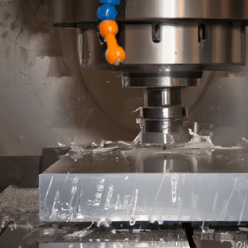
Computer Numerical Control (CNC) machining encompasses a broad range of subtractive manufacturing processes, primarily milling and turning, which are foundational to modern industrial production. These methods precisely remove material from a workpiece using rotating cutting tools or by rotating the workpiece against a stationary tool. The integration of advanced software and hardware allows for unparalleled accuracy and repeatability in part creation.
Subtractive rotary cutting is the core principle behind both CNC milling and turning. In milling, a multi-point cutting tool rotates at high speed while the workpiece remains stationary or moves along linear axes. Conversely, CNC turning involves rotating the workpiece itself against a stationary, single-point cutting tool to generate cylindrical or round features.
Understanding CNC Milling and Turning Principles
CNC milling machines excel at producing prismatic parts and complex three-dimensional surfaces, including blocks, plates, slots, and pockets. The cutting tool, often a multi-flute end mill, moves along multiple axes (X, Y, Z, and often A/B/C for multi-axis machines) to sculpt the desired geometry from solid stock. This versatility makes milling indispensable for intricate component fabrication.
CNC turning is optimized for creating parts with rotational symmetry, such as shafts, pins, bushings, and threaded components. A workpiece is securely clamped in a chuck or collet and spun at controlled revolutions per minute (RPM). A cutting tool then traverses the rotating material, removing chips to form the specified diameter and profile.
Both processes rely on G-code, a standardized programming language that dictates machine movements, tool changes, and cutting parameters. This digital instruction set ensures consistent and repeatable manufacturing, minimizing human error and maximizing efficiency. Modern CAM software generates these complex toolpaths, often incorporating simulation to prevent collisions and optimize material removal.
Turn-Mill Hybrid Machines: Consolidating Operations
| Parameter | CNC Milling (Standard) | CNC Turning (Standard) | Precision Grade |
|---|---|---|---|
| Linear Tolerance (mm) | ±0.05 to ±0.13 | ±0.05 to ±0.13 | ±0.01 to ±0.005 |
| Angular Tolerance (degrees) | ±0.5 | ±0.5 | ±0.25 |
| Surface Finish (Ra µm) | 1.6 – 3.2 | 0.4 – 3.2 | 0.4 (turning) |
Turn-mill hybrid machines represent a significant advancement in CNC technology, combining the capabilities of both milling and turning into a single platform. These multi-tasking machines can perform a wide array of operations, including milling, drilling, tapping, turning, and grooving, all within one setup. This integration drastically reduces the need for multiple machine setups and part handling.
The primary advantage of turn-mill centers is their ability to achieve complete part finishing in a ‘one-hit’ machining strategy. By eliminating the need to transfer parts between separate lathes and mills, manufacturers can significantly shorten cycle times and reduce cumulative errors associated with re-fixturing. This approach is particularly beneficial for complex components requiring both rotational and prismatic features.
Advanced turn-mill machines, such as the Heller HF 5500 FLEX, feature simultaneous 5-axis capabilities and powerful HSK-T spindles, enabling highly complex mill-turn operations. Software enhancements, like Mastercam 2026’s expanded prime turning and pinch turn features, further optimize these hybrid processes, improving efficiency and surface finish by balancing cutting between multiple turrets.
Achieving Complex Part Geometry and Complete Finishing
Producing complex part geometry demands sophisticated CNC capabilities, often extending beyond traditional 3-axis machining. Features like undercuts, thin walls, internal cavities, and compound curves necessitate multi-axis movement and specialized tooling. Five-axis simultaneous machining, for instance, allows the cutting tool to move along five axes concurrently, accessing intricate geometries in a single setup and reducing handling errors.
Modern engineering practices leverage advanced CAD/CAM systems to ensure the integrity of complex designs. These systems simulate toolpaths, detect potential issues, and optimize cutting strategies to maintain structural integrity and achieve dimensional accuracy. This digital foundation is critical for manufacturing parts for aerospace, medical devices, and consumer electronics, where tight tolerances are paramount.
Complete part finishing involves achieving specified surface roughness and aesthetic requirements. Standard as-machined finishes from CNC milling typically range from Ra 1.6 to 3.2 µm (63–125 µin), while turning can achieve finishes as smooth as Ra 0.4 µm. Achieving finer finishes often requires slower finishing passes, sharp tooling, and controlled environments, which can increase machining time and cost.
Multi-Spindle Manufacturing for High-Volume Production
Multi-spindle machines are automatic lathes designed for high-volume, high-precision production environments. These machines feature multiple spindles that operate simultaneously, each dedicated to a specific machining task. This parallel processing capability drastically reduces cycle times and significantly increases output compared to single-spindle machines.
The core advantage of multi-spindle manufacturing lies in its ability to break down complex machining operations across several positions. For example, roughing a profile can occur at one station while finishing the same profile is performed at another, without adding to the overall cycle time. This optimized workflow makes them ideal for producing components like connector bodies, fittings, and fasteners for industries such as automotive and aerospace.
CNC-controlled multi-spindle machines offer enhanced flexibility, allowing for faster changeovers and accommodating more complex geometries. They also integrate seamlessly with digital manufacturing environments, contributing to lower per-unit manufacturing costs and improved scalability. Automation in these systems reduces manual labor, further boosting efficiency and accuracy.
Modern Tolerances, Feeds, and Speeds in Practice
Standard commercial tolerances for CNC machining typically range from ±0.05 mm to ±0.13 mm for most milling and turning operations. For precision-grade applications, tolerances as tight as ±0.01 mm are achievable with careful process control, proper tooling, and experienced operators. Ultra-high precision, such as ±0.005 mm, often requires specialized equipment and temperature-controlled environments.
ISO 2768 is a widely used standard for general tolerances, defining permissible deviations for linear and angular dimensions. ISO 2768-mK, indicating medium dimensional and K-class geometrical tolerances, is a common default for many CNC machined parts, balancing cost and precision. For critical features, Geometric Dimensioning and Tolerancing (GD&T) is recommended alongside ISO 2768.
Optimizing feeds and speeds is critical for maximizing material removal rates, extending tool life, and achieving desired surface finishes. For aluminum, typical milling operations might use 8,000–12,000 RPM with feed rates of 40–80 IPM for a 2-flute end mill, with chip loads around 0.001–0.003 inches per tooth. For turning mild steel, cutting speeds around 180 m/min are common, with roughing feeds of 0.25–0.5 mm/rev and finishing feeds of 0.05–0.15 mm/rev.
The selection of feeds and speeds is highly dependent on material properties, tool geometry, and machine rigidity. Higher RPM is often necessary for smaller tools in aluminum to achieve optimal cutting speeds, while harder materials like titanium require specialized tooling and rigid setups to prevent chatter.