
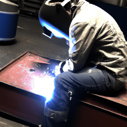
Producing high-quality welds consistently requires a deep understanding and precise control of several fundamental parameters. Mastering these elements ensures structural integrity, optimal mechanical properties, and a visually appealing weld bead. Neglecting any of these critical factors can lead to costly defects and compromised project timelines.
Modern welding operations, from intricate fabrication to heavy construction, rely on skilled operators who can accurately adjust machine settings and maintain proper technique. This technical guide explores the essential parameters that underpin successful welding, providing insights into current best practices and safety protocols.
Optimizing Amperage and Voltage Settings
Amperage, or welding current, directly controls the heat input into the workpiece, dictating the depth of weld penetration. Higher amperage generates more heat, which is necessary for welding thicker materials, while lower amperage is suitable for thinner sections to prevent burn-through [30]. Incorrect amperage can lead to significant defects, such as insufficient penetration if too low, or excessive melt-through if too high [10, 20].
Voltage, the electrical pressure creating the arc, primarily influences the arc length and the width of the weld puddle [30]. Proper voltage settings ensure a stable arc and a consistent bead profile. Too little voltage can result in poor arc starts and control, while excessive voltage leads to poor arc control, inconsistent penetration, and a turbulent weld pool [20].
For MIG welding, material thickness often determines the starting amperage, with a general rule of thumb being approximately 1 amp per 0.001 inch of material thickness [31]. For example, 1/4 inch mild steel MIG welding typically requires 180–250 amps and 20–25 volts, using a .035 wire at 280–420 IPM with 75/25 argon/CO2 gas [9]. TIG welding, known for its precision, also follows a similar ‘1 amp per 0.001 inch’ rule for steel thickness, meaning 1/8 inch steel would require around 125 amps [13].
Many contemporary welding machines feature advanced controls like pulse and synergic settings, which automatically optimize amperage and voltage for specific materials and thicknesses. These features help maintain consistent heat input, reduce distortion, and improve overall efficiency, making them invaluable for professional and industrial applications [13]. Welders should always run a test bead on scrap material to fine-tune settings for optimal results, as conditions vary by machine, joint fit-up, position, and ambient factors [9, 30].
Mastering Travel Speed Control
| Process | Material Thickness | Amperage (A) | Voltage (V) | Wire Feed Speed (IPM) | Shielding Gas | Gas Flow (CFH) |
|---|---|---|---|---|---|---|
| MIG (GMAW) | 1/8″ (3.2mm) | 140-180 | 17-19 | 180-300 | 75% Ar / 25% CO₂ | 25-30 |
| MIG (GMAW) | 1/4″ (6mm) | 180-250 | 20-25 | 280-420 | 75% Ar / 25% CO₂ | 30-40 |
| TIG (GTAW) | 1/8″ (3.2mm) | ~125 | N/A | N/A | 100% Argon | 15-25 |
| Stick (SMAW) | 1/8″ (3.2mm) | 70-125 | N/A | N/A | N/A | N/A |
Travel speed, the rate at which the welding torch or gun moves across the workpiece, is a critical variable that significantly impacts weld quality and efficiency [8]. Alongside amperage and voltage, travel speed determines the total heat input into the weld, influencing penetration, bead profile, and the likelihood of defects [8]. Maintaining the arc on the leading edge of the puddle is generally indicative of proper travel speed [20].
Moving too slowly can result in excessive weld deposition, leading to an overly wide weld, slag inclusions, and potential burn-through, especially on thinner materials due to excessive heat transfer [8, 20]. A large weld pool can ‘cushion’ the arc, reducing its ability to penetrate the base metal, which may cause lack of fusion or ‘cold lapping’ [8]. Conversely, a travel speed that is too fast prevents the arc from adequately melting the base material, resulting in a thin, narrow weld with poor fusion and insufficient penetration [8, 20].
Different welding processes react distinctly to travel speed variations. MIG welding is particularly sensitive, where higher speeds can lead to insufficient penetration, while slower speeds risk distortion and burn-through [28]. TIG welding, being a precise process, also sees significant quality impacts from travel speed, with slower speeds increasing the likelihood of distortion [28]. For stick welding, slower speeds are generally preferred to ensure better penetration, though electrode angle and technique remain crucial [28].
Implementing Proper Joint Preparation
The quality of a weld is fundamentally dependent on the preparation of the joint; inadequate preparation is a leading cause of weld failure [11]. Proper joint preparation ensures optimal weld penetration, fusion, and minimizes defects such as porosity, lack of fusion, and incomplete penetration [6, 23, 25]. This crucial stage involves several key steps, beginning with thorough cleaning.
Cleaning the metal surface is non-negotiable, as contaminants like rust, oil, paint, and mill scale interfere with proper fusion, leading to porosity and other defects [3, 6, 11, 27]. Surfaces should be cleaned within an inch of the joint on both sides, using methods such as chemical degreasing, wire brushing, or grinding [11, 17, 21]. For stainless steel and aluminum, dedicated stainless-steel brushes or grinding wheels must be used to prevent cross-contamination [21]. Solvent cleaning should always precede grinding to avoid embedding oils into the metal’s pores, followed by a second cleaning to remove grinding dust [11].
Cutting, fitting, and beveling are also essential. Beveling involves angling the edges of metal pieces to create a V-shaped groove, which enhances weld strength and filler penetration, particularly for materials 3/16 inch or thicker [11, 23]. A common V-groove design calls for a 60-degree included angle (30 degrees per side) with a root opening of 1/16 to 1/8 inch, depending on the joint type [11, 21]. It is important to leave a ‘land’ of 1/16 to 1/8 inch thickness at the edge to support the arc’s heat and prevent a knife-like edge from blowing away [21]. Proper fit-up and alignment, often secured with tack welds, ensure the materials remain in position during the main welding process [25]. MIG and TIG welding generally demand cleaner surfaces and more meticulous preparation than stick welding [11, 17].
Ensuring Adequate Shielding Gas Coverage
Shielding gas is indispensable in arc welding processes like MIG and TIG, as it protects the molten weld pool and the arc from atmospheric contamination by oxygen, nitrogen, and hydrogen [1, 18]. Without proper shielding, these gases can cause severe weld defects such as porosity, embrittlement, and reduced mechanical strength [1, 2, 6, 27]. The choice of shielding gas significantly influences arc stability, heat transfer, penetration, and the final weld bead appearance [1, 18].
Common shielding gases include pure argon, argon-CO2 blends, and pure CO2. Pure argon is widely used for TIG welding and for MIG welding aluminum due to its stable arc and good ionization properties [1, 16, 24]. For mild steel MIG welding, a blend of 75% argon and 25% CO2 (C25) is a popular choice, offering a stable arc, reduced spatter, and good penetration [9, 18]. Pure CO2 provides deeper penetration but can result in more spatter and a less stable arc [1, 18]. Helium, sometimes added to argon, increases heat input and penetration, particularly for thicker aluminum or copper, though it requires higher flow rates due to its lower density and is more costly [1, 15, 18].
Setting the correct shielding gas flow rate is critical. Most MIG and TIG applications typically require a flow rate between 20 and 30 cubic feet per hour (CFH) [1]. A flow rate that is too low allows ambient air to contaminate the weld pool, causing porosity [1, 18]. Conversely, an excessively high flow rate can create turbulence, which paradoxically pulls atmospheric air into the weld area, also leading to porosity [1, 18]. Factors such as nozzle size, breezy conditions, or out-of-position welding may necessitate modest adjustments to the flow rate [1]. For stainless steel, a higher flow rate of 25-30 CFH is often recommended due to its sensitivity to contamination, increasing to 40-50 CFH for helium-based trimix gases [18].
Utilizing Essential Safety Equipment
Welding presents numerous hazards, including intense heat, sparks, molten metal, harmful UV and infrared radiation, and toxic fumes [14]. Therefore, the diligent use of appropriate personal protective equipment (PPE) is not merely a recommendation but a non-negotiable requirement to prevent injuries and ensure compliance with safety standards like OSHA 1910.252 and CSA W117.2 [7, 12, 22]. PPE serves as the final safeguard when other controls cannot eliminate hazards [22].
Essential PPE for welders includes a high-quality welding helmet with the correct shade filter. Modern helmets often feature auto-darkening lenses with a 1/1/1/1 optical clarity rating, which significantly reduces eye strain and provides superior vision [7, 12]. Flame-resistant (FR) clothing, made from materials like treated cotton or leather, is crucial to protect against sparks and heat [7, 14]. This clothing must cover all exposed skin, with no rolled-up sleeves or gaps between gloves and sleeves, and pants should lack cuffs to prevent spark collection [7].
Leather gauntlet gloves are necessary to protect hands from heat and sparks, while safety footwear, preferably high-top leather work boots, shields feet from falling objects and molten metal [7, 14, 19]. Hearing protection is vital in noisy welding environments [7, 22]. Furthermore, advanced respiratory protection systems, such as Powered Air-Purifying Respirators (PAPRs), are increasingly recommended in 2026 to protect against welding fumes and dust, offering high filtration efficiency and integrated eye protection [12, 19]. Regular inspection of all PPE is critical to identify and replace damaged gear, as even minor defects can compromise safety [7, 12].