
Computer Numerical Control (CNC) machining encompasses a broad range of subtractive manufacturing processes, with milling and turning standing as two foundational methods. Both leverage automated control to remove material from a workpiece, yet their operational mechanics and resulting part geometries differ significantly. Understanding these distinctions is critical for engineers and machinists to select the optimal process for specific component requirements.
Choosing between CNC milling and turning directly impacts production efficiency, achievable tolerances, surface finish, and overall manufacturing cost. The core difference lies in how the cutting action is achieved, influencing everything from tool selection to machine kinematics. This technical guide explores the fundamental disparities between these two prevalent CNC operations.
Fundamental Kinematics: Tool versus Part Rotation
CNC milling involves a stationary workpiece, typically clamped to a machine table, while a rotating cutting tool removes material. The tool, often an end mill or face mill, spins at high speeds and moves along multiple axes to carve the desired shape. This setup is ideal for creating complex three-dimensional geometries, pockets, and intricate contours.
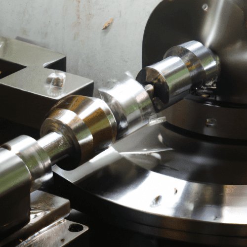
Conversely, CNC turning operates by rotating the workpiece at high speed, while a stationary, non-rotating cutting tool engages its surface. The tool moves linearly along and across the rotating part, removing material to generate cylindrical or round features. This method is exceptionally efficient for producing parts with rotational symmetry, such as shafts, pins, and bushings.
The defining kinematic difference is straightforward: in milling, the tool spins and the part remains fixed; in turning, the part spins and the tool remains largely stationary, moving only to control the cut. This fundamental distinction dictates the types of geometries each process can effectively create.
Geometric Outcomes: Planar versus Cylindrical Machining
| Parameter | CNC Milling | CNC Turning |
|---|---|---|
| Primary Motion | Rotating Tool, Stationary Part | Rotating Part, Stationary Tool |
| Typical Part Geometry | Flat surfaces, complex 3D shapes, pockets, slots | Cylindrical, conical, spherical, threaded features |
| Cutting Tools | Multi-point (end mills, face mills, drills) | Single-point (turning inserts, boring bars) |
| Standard Tolerance (mm) | ±0.05 mm (±0.002″) | ±0.05 mm (±0.002″) |
| Precision Tolerance (mm) | ±0.01 mm (±0.0004″) | ±0.025 mm (±0.001″) |
| Typical Feeds & Speeds (Al 6061) | Vc: 300-1200 m/min, fz: 0.05-0.15 mm/tooth | N/A (not primary for Al turning) |
| Typical Feeds & Speeds (SS 304) | Vc: 60-75 m/min, fz: 0.05-0.15 mm/tooth | Vc: 100-220 m/min, f: 0.05-0.40 mm/rev |
| Chip Formation | Intermittent, C-shaped, 6-shaped, discontinuous | Continuous, spiral, C-shaped (with chip breakers) |
Milling excels at producing flat surfaces, intricate profiles, and complex three-dimensional forms. The multi-axis movement of the cutting tool allows for the creation of features like slots, pockets, chamfers, and contoured surfaces on various faces of a workpiece. This versatility makes milling indispensable for components requiring non-rotational symmetry.
Turning, by its nature, is optimized for generating parts with rotational symmetry. It efficiently produces external and internal cylindrical features, tapers, threads, and grooves. Operations such as facing, boring, and profiling are standard on a CNC lathe, resulting in components that are perfectly round or have concentric features.
Modern turn-mill machines combine both capabilities, allowing for the creation of complex parts with both rotational and non-rotational features in a single setup. This hybrid approach significantly reduces setup times and improves overall part accuracy by eliminating the need to transfer workpieces between different machines.
Cutting Edge Mechanics: Multi-Point and Single-Point Tools
Milling operations predominantly utilize multi-point cutting tools, such as end mills, face mills, and slab mills. These tools feature multiple cutting edges (flutes) that engage the workpiece intermittently as the tool rotates. Each flute takes a small chip, distributing the cutting load and heat across several edges.
This multi-point engagement contributes to higher material removal rates and generally longer tool life compared to single-point tools in similar roughing applications. The design of these tools, including helix angle and coating, is optimized for efficient chip evacuation and heat dissipation during intermittent cutting.
Turning, conversely, primarily employs single-point cutting tools, often in the form of indexable inserts. These tools have only one active cutting edge in continuous contact with the workpiece. The entire chip load and cutting forces are concentrated on this single edge, demanding robust tool materials and geometries.
While single-point tools may have lower material removal rates than multi-point tools for roughing, they offer superior precision and surface finish, especially for critical diameters and intricate profiles. Their simpler geometry also makes them easier to sharpen or replace.
Axis Configurations and Motion Control Systems
CNC milling machines typically operate with a minimum of three linear axes (X, Y, Z), allowing movement along horizontal and vertical planes. More advanced mills incorporate additional rotary axes (A, B, C) to enable machining on multiple sides of a part or continuous contouring.
A 4-axis mill adds one rotary axis, often rotating the workpiece, enabling machining of features on four sides or helical interpolation. 5-axis machines introduce two rotary axes, allowing the tool to approach the workpiece from virtually any angle, crucial for complex aerospace components or impellers.
CNC lathes traditionally feature two linear axes: X (radial movement, controlling diameter) and Z (longitudinal movement, along the spindle axis). Modern turning centers, particularly turn-mill machines, can integrate additional axes, such as a Y-axis for off-center drilling and milling, or a C-axis for controlled spindle rotation.
These multi-axis turning centers, sometimes reaching 12 axes, significantly expand the range of features that can be completed in a single setup, reducing part handling and improving accuracy. The B-axis, for instance, often refers to a tilting milling spindle on advanced turn-mill configurations.
Material Removal Dynamics: Understanding Chip Formation Patterns
Chip formation is a critical indicator of machining efficiency and tool health in both milling and turning. During material removal, the workpiece undergoes plastic deformation and shearing, forming chips that carry away a significant portion of the heat generated. Ideal chips are typically short, tightly curled, and easily evacuated.
In milling, chip formation is intermittent due to the rotating, multi-point tool engaging and disengaging the workpiece. Proper chip load per tooth is essential to prevent ‘rubbing’ (too thin a chip) or excessive tool pressure (too thick a chip), both of which can lead to poor surface finish, built-up edge, or premature tool wear.
Turning, with its continuous cutting action, often produces longer, more continuous chips, especially in ductile materials like aluminum or mild steel. Chip breakers are frequently integrated into turning inserts to curl and fracture these long chips into manageable segments, preventing entanglement and ensuring safe, efficient operation.
Different materials exhibit distinct chip formation characteristics. Brittle materials like cast iron tend to form discontinuous chips, while ductile materials like aluminum often produce continuous chips. Stainless steels, known for work hardening, can form non-homogeneous or serrated chips, requiring careful adjustment of feeds and speeds to maintain a consistent cut.