
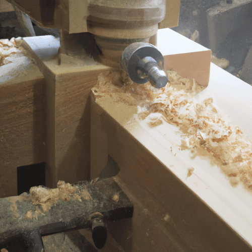
Machining wood involves a diverse array of processes, from automated CNC routing to traditional planing and sawing, each demanding specific technical understanding for optimal results. The inherent anisotropic nature of wood, characterized by its grain structure, moisture content, and density variations, presents unique challenges and opportunities for engineers and machinists.
Achieving precise dimensions, superior surface finishes, and efficient material removal necessitates a deep dive into tooling selection, operational parameters, and environmental controls.
CNC Wood Routing for Intricate Designs
Computer Numerical Control (CNC) wood routing has become indispensable for producing complex geometries and repeatable parts with high accuracy. The choice of router bit material significantly impacts performance and tool life; High-Speed Steel (HSS) bits are more economical and easier to sharpen, suitable for softer woods, while carbide-tipped or solid carbide bits offer superior durability and edge retention, making them ideal for hardwoods, engineered wood products, and abrasive materials like MDF.
Optimizing feeds and speeds is critical to prevent burning, tear-out, and premature tool wear. Spindle speeds for CNC routers typically range from 8,000 to 24,000 RPM, with larger diameter bits generally requiring lower RPMs to maintain appropriate surface speeds.
Chip load, the amount of material removed by each cutting edge per revolution, is a fundamental parameter, with recommended values often falling between 0.003-0.004 inches per tooth for softwoods, hardwoods, and plywood, and slightly higher for MDF.
Axial depth of cut (DOC) guidelines suggest not exceeding 1x the bit diameter for softwoods and 0.5x for hardwoods, reducing to 0.5x diameter for full-width slotting cuts to manage tool load.
Standard tolerances for CNC routing typically fall within ±0.005 inches (0.13 mm), though tighter tolerances down to ±0.001 inches are achievable with specialized setups and meticulous process control. Router bit geometries, such as upcut, downcut, and compression spirals, are selected based on desired chip evacuation, surface finish, and workpiece hold-down requirements.
Upcut bits lift chips, downcut bits push them down, and compression bits combine both actions for clean top and bottom edges, particularly useful in veneered plywood or laminates. V-bits are employed for engraving and chamfering, offering precise angular cuts.
Achieving Flatness with Planing and Jointing
| Material Type | RPM (Revolutions Per Minute) | Feed Rate (IPM / mm/min) | Chip Load (IPT / mm/tooth) | Max DOC (Axial Depth of Cut) |
|---|---|---|---|---|
| Softwoods (Pine, Cedar) | 16,000-18,000 | 100-150 IPM (2540-3810 mm/min) | 0.003-0.004″ (0.076-0.102 mm) | 1x Bit Diameter |
| Hardwoods (Oak, Maple) | 16,000-18,000 | 80-120 IPM (2032-3048 mm/min) | 0.003-0.004″ (0.076-0.102 mm) | 0.5x Bit Diameter |
| Plywood (Baltic Birch) | 16,000-18,000 | 100-140 IPM (2540-3556 mm/min) | 0.003-0.004″ (0.076-0.102 mm) | 1x Bit Diameter |
| MDF (Medium Density Fiberboard) | 16,000-18,000 | 100-150 IPM (2540-3810 mm/min) | 0.003-0.005″ (0.076-0.127 mm) | 1x Bit Diameter |
Planing and jointing are foundational woodworking operations aimed at creating flat and square stock, essential for accurate joinery and stable assemblies. A jointer establishes one flat face and one square edge, while a thickness planer then machines the opposing face parallel to the first, achieving a consistent thickness.
These processes are critical for dimensioning rough lumber into usable material.
Cutterhead technology significantly influences the quality of the machined surface. Traditional straight-knife cutterheads, typically equipped with 2-4 long blades, strike the entire width of the board simultaneously, which can lead to increased noise, vibration, and tear-out, especially on figured or reversing grain.
Helical cutterheads, conversely, feature numerous small, square carbide inserts arranged in a spiral pattern, each mounted at a fixed shear angle. This design creates a shearing cut rather than a chopping action, resulting in significantly lower noise levels, reduced tear-out, and a smoother surface finish that often requires minimal sanding.
Furthermore, individual inserts can be rotated or replaced when dull, extending tool life and simplifying maintenance compared to sharpening or replacing entire straight knives.
Achievable tolerances in planing and jointing are crucial for subsequent operations. For general woodworking, flatness and thickness tolerances are typically within ±0.005 to ±0.010 inches across the width and length of a board.
Precision applications may demand tighter control, especially when preparing stock for intricate joinery where cumulative errors can lead to significant fitment issues. Regular calibration of machines, sharp tooling, and appropriate feed rates are paramount to maintaining these tolerances and preventing defects like snipe or uneven stock removal.
Precision in Sawing and Shaping Operations
Sawing operations are fundamental for breaking down raw lumber and sheet goods into manageable components, while shaping creates specific profiles and contours. The selection of saw blade and cutting parameters directly impacts material yield, cut quality, and operational safety.
Kerf, the width of the material removed by the saw blade, is a critical consideration.
Saw blades are categorized by their kerf width: thin kerf blades (approximately 3/32 inch) remove less material, requiring less power and maximizing lumber yield, making them suitable for lower-powered saws or expensive hardwoods.
Standard or full kerf blades (typically 1/8 inch) offer greater rigidity, reducing deflection and vibration, which is advantageous for heavy workloads and maintaining a straighter cutting path in production environments.
The tooth count, hook angle, and grind geometry of a blade are selected based on the material and desired cut quality, with higher tooth counts generally yielding smoother crosscuts and lower tooth counts being more efficient for ripping along the grain.
Shaping operations, performed on router tables or dedicated shapers, are used to create decorative edges, joinery profiles, and custom millwork. Shapers, with their larger spindles and more powerful motors, can accommodate larger diameter and heavier profile cutters than most routers, making them the preferred choice for production woodworking and extensive edge profiling on solid wood.
Shaper cutters are typically made from micrograin carbide, which maintains a sharp edge longer and produces a cleaner, smoother cut surface, minimizing post-machining sanding. The robust nature of shapers allows for deeper cuts and faster feed rates, enhancing efficiency in high-volume applications.
Navigating Wood Grain for Optimal Results
Understanding wood grain is paramount in machining, as its orientation profoundly influences cutting behavior and surface finish. Wood is composed of long cellulose fibers, and cutting against the grain, or ‘uphill’ on the fibers, significantly increases the likelihood of tear-out, splintering, and rough edges.
This occurs when the cutting tool lifts and fractures wood fibers ahead of the cut rather than cleanly shearing them.
To mitigate tear-out, several strategies are employed. Aligning the tool path with the wood grain allows the cutting blades to move smoothly along the natural fibers. For CNC routing, climb milling (down milling), where the cutter rotates in the same direction as the feed, is generally preferred for wood as it typically produces a better surface finish and extends tool life by reducing friction and heat.
The chip thickness starts at its maximum and thins out, leading to cleaner shearing. Conversely, conventional milling (up milling) can cause the tool to rub more at the beginning of the cut, increasing heat and tool wear, and potentially leading to a rougher finish.
Beyond grain direction, other factors contribute to tear-out and burning. Dull router bits are a primary cause, as they rip rather than slice fibers, increasing friction and heat. Incorrect feed rates—either too fast, not allowing the bit enough time to cut cleanly, or too slow, causing excessive friction and burning—also degrade cut quality.
The moisture content of the wood is also relevant; overly dry wood can be brittle and prone to tear-out, while excessively moist wood may increase cutting resistance and burning.
Implementing Robust Dust Collection Systems
Effective dust collection is not merely a matter of shop cleanliness but a critical engineering control for worker health and machine longevity. Wood dust, particularly fine particulate matter, poses significant respiratory health risks, including dermatitis, allergic reactions, asthma, chronic bronchitis, and even nasal cancer, especially from certain hardwoods like oak and mahogany.
The Occupational Safety and Health Administration (OSHA) sets permissible exposure limits (PELs) for wood dust, recommending 5 mg/m³ for softwood dust and 1 mg/m³ for hardwood dust over an 8-hour workday, with stricter limits for specific species like Western Red Cedar.
Local Exhaust Ventilation (LEV) systems are the primary method for controlling wood dust, capturing it at or near the source. These systems range from portable shop vacuums for handheld tools (typically 150-200 CFM) to single-stage collectors (500-1,000 CFM for small shops) and industrial two-stage cyclone systems (1,000-2,000+ CFM for larger operations).
Cyclone separators are highly efficient, exceeding 99% efficiency by weight in separating bulk chips and larger dust particles before they reach the final filter, thus preventing premature clogging and maintaining airflow.
Ducting design is crucial for system performance, requiring minimum duct velocities of 2,500 to 4,000 feet per minute to effectively transport dust and chips and prevent clogging. Filter selection is equally important; while standard pleated filters capture larger particles, HEPA filters are certified to capture at least 99.97% of particles at 0.3 microns, providing superior protection against fine, respirable dust.
Regular inspection and cleaning of ducts, filters, and fan belts are essential to ensure the LEV system operates at peak efficiency and maintains compliance with safety standards.