
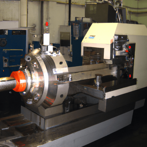
The lathe stands as a foundational machine tool in modern manufacturing, indispensable for creating components with rotational symmetry. This versatile equipment rotates a workpiece about an axis while a stationary cutting tool removes material, shaping the part to precise specifications. Its core purpose involves producing perfectly round, centered, or axially uniform components, including shafts, bores, and threads, often to tight dimensional tolerances.
Lathes are crucial across numerous industries, from aerospace and defense to automotive and medical device manufacturing. Both manual and advanced CNC lathes are common, with CNC models offering enhanced precision, efficiency, and flexibility through automation and real-time optimization. These machines are capable of executing a variety of operations, each contributing to the final form and function of a component.
Generating Precise Cylindrical Forms
External turning, the most common lathe operation, involves reducing the diameter of a workpiece to create a cylindrical surface of a desired length. This process systematically removes excess material, ensuring the component achieves specific dimensional requirements and concentricity. Achieving a consistent diameter along the entire turned length is paramount for proper assembly and function.
Precision in turning operations often demands tight tolerances and specific surface finishes. Standard CNC turning typically achieves tolerances around ±0.005 inches (±0.13 mm) for most linear dimensions, with high-precision applications reaching ±0.001 inches (±0.025 mm) or better. Surface roughness, measured in Ra (roughness average), commonly ranges from 0.8 to 1.6 µm for general turning, with finer finishes down to 0.2 µm Ra possible for critical sealing or bearing surfaces.
Tooling for turning operations typically includes high-speed steel (HSS) or carbide inserts, selected based on workpiece material and desired finish. Carbide inserts are favored for their heat resistance and ability to maintain a sharp edge at higher cutting speeds. Proper feeds and speeds are critical for optimal material removal, tool life, and surface integrity, requiring careful calculation based on material hardness, tool geometry, and machine rigidity.
Crafting Accurate Threads
| Parameter | Aluminum (6061-T6) | Mild Steel (1018) | Stainless Steel (304) |
|---|---|---|---|
| Cutting Speed (SFM) – Carbide | 600 – 1200 | 100 – 150 | 60 – 70 |
| Feed Rate (IPR) – Roughing | 0.004 – 0.010 | 0.005 – 0.015 | 0.003 – 0.008 |
| Feed Rate (IPR) – Finishing | 0.002 – 0.005 | 0.002 – 0.008 | 0.001 – 0.004 |
| Standard Tolerance (inches) | ±0.005 – ±0.010 | ±0.005 – ±0.010 | ±0.005 – ±0.010 |
| Typical Surface Finish (Ra µm) | 0.8 – 1.6 | 1.6 – 3.2 | 1.6 – 3.2 |
Precision thread cutting on a lathe involves generating helical grooves on external or internal cylindrical surfaces. This operation creates fasteners, lead screws, and other components requiring specific mating capabilities. The accuracy of the thread’s lead, pitch, and form is critical for its intended mechanical engagement.
Lathes can produce various thread forms, including Unified National (UNC, UNF), Metric (M), and Acme threads, each with distinct profiles and applications. The process requires precise synchronization between the spindle rotation and the axial movement of the cutting tool, controlled by the lead screw or CNC programming. Specialized threading inserts are designed to match the specific thread profile, ensuring accurate geometry and smooth engagement.
Modern CNC lathes excel at thread generation, offering advanced control over cutting parameters and multi-pass strategies to achieve high-quality threads efficiently. These machines can compensate for tool wear and material variations, producing consistent threads with minimal manual intervention. The ability to program complex thread cycles reduces setup time and improves repeatability for production runs.
Achieving Flat and Perpendicular Faces
Facing is a fundamental lathe operation that removes material from the end of a workpiece to produce a flat, smooth surface perpendicular to its rotational axis. This process is essential for establishing a datum surface, reducing workpiece length, or preparing a surface for subsequent operations like drilling or assembly.
Proper tool setup is vital for successful facing, with the cutting tool’s tip positioned precisely at the centerline of the workpiece. Starting cuts slightly off-center and feeding outward is a common technique to prevent the formation of a ‘center pip’ and achieve a superior finish. Conversely, feeding from the outside diameter towards the center is also common, especially for roughing passes.
Factors influencing facing quality include tool angle, cutting speed, and workpiece stability. As the tool approaches the center, the surface speed decreases, often requiring adjustments to the feed rate to maintain a consistent surface finish. Using light finishing passes and ensuring the cross-slide is perpendicular to the spindle axis helps achieve optimal flatness and surface quality.
Enlarging and Refining Internal Bores
Boring on a lathe involves enlarging or refining an existing hole to a precise internal diameter and desired surface finish. This operation is critical for creating accurate bearing seats, housing fits, or other internal features requiring tight dimensional control and concentricity. Boring can achieve superior accuracy and surface finish compared to drilling alone, especially for deeper holes or when strict tolerances are required.
Boring bars, which hold the cutting insert, must possess sufficient rigidity to prevent chatter and deflection during the cut. Minimizing tool overhang and selecting appropriate boring bar diameters are crucial for maintaining stability and achieving the specified hole geometry. Coolant application is also important to manage heat and aid chip evacuation, particularly in deep boring operations.
Achieving precise internal diameters often requires multiple passes, starting with roughing cuts to remove bulk material and progressing to fine finishing passes. Tolerances for bored holes can be exceptionally tight, often within ±0.0005 inches (±0.0127 mm) for critical applications. Careful measurement and adjustment are necessary throughout the boring process to ensure the final dimension meets engineering specifications.
Efficiently Separating Components
Parting off, also known as cutoff, is a lathe operation used to separate a finished or semi-finished component from the larger stock material. This is typically one of the final operations performed on a turned part, creating individual pieces of specific lengths. While seemingly straightforward, parting off requires careful execution to avoid common pitfalls.
The operation utilizes a narrow, blade-style tool that feeds radially into the rotating workpiece, creating a groove until the part separates. Key challenges include poor chip evacuation, which can lead to chip jamming and tool breakage, and tool deflection due to the high length-to-width ratio of the parting blade. Heat generation is also significant, especially as the tool approaches the center of the workpiece where surface speed diminishes.
To ensure a clean and safe parting operation, maximizing tool stiffness by minimizing overhang is essential. The parting tool must be set precisely on the centerline of the workpiece to prevent improper cutting and tool damage. For manual lathes, using ample cutting fluid and employing peck cuts to break chips are recommended practices. CNC lathes can optimize feed rates and spindle speeds dynamically to manage these challenges effectively.