
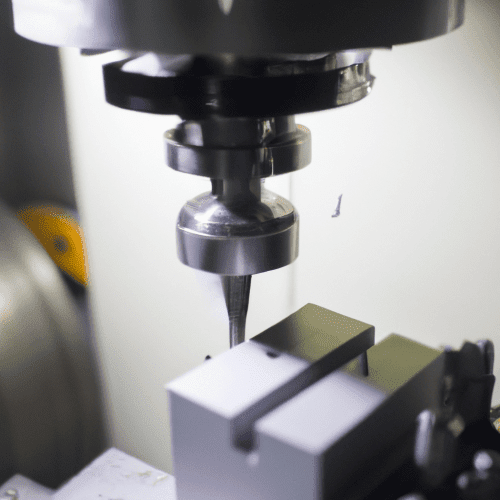
Computer Numerical Control (CNC) engineering integrates design, programming, and machining to produce parts with exceptional accuracy and repeatability. This discipline encompasses a broad range of technical skills, from initial concept development to final part inspection. It is fundamental to industries requiring high-precision components, driving innovation across sectors like aerospace, medical, and automotive.
CAD Design for Manufacturing
Computer-aided design (CAD) serves as the foundational step in any CNC manufacturing workflow. Engineers meticulously create detailed 2D and 3D models of components, defining precise geometries, critical dimensions, and material specifications. Modern CAD software offers robust tools for complex surface modeling, solid modeling, and large-scale assembly design, enabling intricate part creation.
Designing for Manufacturability (DFM) principles are integrated early in the CAD process to optimize part designs for efficient and cost-effective production. This involves careful consideration of material selection, minimizing overly complex features, and ensuring adequate wall thicknesses to prevent warping, chatter, or tool breakage during machining. Early DFM application significantly reduces production costs, shortens lead times, and improves overall part quality.
Current CAD platforms like SolidWorks, Autodesk Fusion 360, and CATIA provide advanced simulation and analysis capabilities. These powerful tools allow engineers to analyze stress distribution, thermal performance, and even simulate machining operations to identify potential issues before any physical material is cut. This virtual prototyping minimizes costly errors and refines designs for optimal performance and manufacturability.
Toolpath Optimization
| Parameter | Aluminum 6061 (Carbide End Mill) | 304 Stainless Steel (Carbide End Mill) |
|---|---|---|
| Cutting Speed (SFM) | 1000 – 4000 (Roughing: 800-1200, Finishing: 1000-1500+) | 200 – 250 |
| Chip Load (per tooth) | 0.001″ – 0.005″ | 0.002″ – 0.006″ (0.05 – 0.15 mm) |
| Spindle Speed (RPM) | 6,000 – 20,000 (e.g., 0.5″ end mill at 1000 SFM is ~7640 RPM) | 3,000 – 5,000 (for 10mm tool) |
| Feed Rate (IPM) | Calculated (e.g., 70-90 IPM for 3/16″ end mill) | 15 – 30 (for 0.5″ end mill, 4 flutes) |
Toolpath optimization focuses on generating the most efficient and effective cutting strategies for a given part, material, and machine tool. This critical process involves selecting appropriate cutting tools, defining precise cutting depths, stepovers, and machining sequences to minimize cycle time, maximize material removal rates, and extend tool life. Advanced Computer-Aided Manufacturing (CAM) software is indispensable for this process.
Modern CAM systems employ sophisticated algorithms for generating highly optimized toolpaths, including advanced high-speed machining (HSM) techniques. HSM paths are characterized by maintaining a constant tool engagement angle and consistent chip load, which significantly reduces heat buildup at the cutting edge and extends tool life, particularly when machining hard materials. This approach often utilizes smaller radial depths of cut combined with higher feed rates and spindle speeds.
Strategies like trochoidal milling are frequently employed for slotting and roughing operations, especially in tough materials such as stainless steel or titanium. This method involves the tool moving in a circular path while simultaneously advancing linearly, effectively clearing chips and reducing cutting forces. Adaptive clearing is another popular technique that dynamically adjusts the toolpath to maintain a consistent material removal rate, preventing sudden load changes on the tool.
Fixture and Workholding Design
Effective fixture and workholding design is paramount for achieving precision, repeatability, and safety in CNC machining operations. Fixtures are custom-engineered devices that securely locate and support the workpiece, preventing any movement or vibration during aggressive cutting operations. Proper workholding ensures consistent part positioning relative to the machine’s coordinate system, which is vital for dimensional accuracy.
Common workholding devices include precision vises, hydraulic clamps, collet chucks, and custom-designed jigs tailored to specific part geometries. The design process meticulously considers factors such as part geometry, material properties, required clamping forces, and clear accessibility for all cutting tools. A well-designed fixture minimizes setup time, reduces the risk of part deformation, and enhances operator safety.
Standard tolerances for fixture components often fall within ±0.0005 to ±0.002 inches (±0.0127 to ±0.0508 mm) to ensure accurate and repeatable part location. This inherent precision in the fixture itself is critical for maintaining tight dimensional control on the final machined part. Modular fixturing systems offer significant flexibility for handling various part geometries, reducing the need for entirely new custom fixtures for every unique job.
Manufacturing Process Planning
Manufacturing process planning outlines the entire logical sequence of operations required to transform raw material into a finished component. This highly detailed plan encompasses machine selection, specific tooling requirements, the precise order of operations, critical quality control checkpoints, and estimated cycle times. It effectively bridges the crucial gap between engineering design and physical production.
Engineers meticulously determine the most efficient order of machining operations, carefully considering factors like optimal material removal, required surface finish, and interdependencies between features. For instance, roughing operations typically precede finishing passes to remove bulk material, and critical features are often machined last to maintain the highest accuracy. This systematic approach minimizes errors and optimizes material flow.
Lean manufacturing principles are frequently integrated into process planning to identify and systematically eliminate waste throughout the production cycle. This includes optimizing material flow, reducing non-value-added steps, minimizing work-in-progress inventory, and streamlining changeovers. The overarching goal is to achieve maximum efficiency, cost-effectiveness, and consistent quality throughout the entire manufacturing process.
G-Code Development
G-code, often referred to as ‘preparatory code,’ is the fundamental programming language that directly instructs CNC machines on how to operate. It dictates precise tool movements, spindle speeds, feed rates, coolant activation, and numerous other machine functions. While advanced CAM software generates the vast majority of G-code, a solid understanding of its structure and commands is vital for debugging, optimization, and manual intervention.
Common G-code commands include G00 for rapid traverse (non-cutting movement), G01 for linear interpolation (controlled feed rate cutting), G02/G03 for circular interpolation (clockwise/counter-clockwise arcs), and M03/M05 for spindle start/stop. Each line of G-code typically specifies a single action or movement, building a comprehensive sequence of operations that the machine executes sequentially.
Manual G-code editing is sometimes necessary for fine-tuning toolpaths, adding specific machine functions not automatically generated by CAM, or troubleshooting unexpected issues on the shop floor. Engineers might manually adjust feed rates, modify rapid traverse points, or insert dwell commands (G04) to improve surface finish, ensure proper chip evacuation, or allow for thermal stabilization. This direct interaction with the machine’s language provides granular control over the machining process.
Key CNC Machining Parameters
Achieving optimal results in CNC machining relies on carefully selected parameters, which are highly dependent on the material, tooling, and machine capabilities. The table below provides typical starting points for common materials, though actual values will require fine-tuning based on specific application, machine rigidity, and desired surface finish. These parameters are crucial for balancing material removal rates with tool longevity and part quality.
Machining tolerances are also a critical consideration, defining the allowable deviation from nominal dimensions for a part to function correctly. Standard CNC machining tolerances for most metals typically range from ±0.005 inches (±0.127 mm), representing a balance between precision and cost for non-critical features. For high-precision applications, such as aerospace or medical components, tolerances can tighten significantly to ±0.001 inches (±0.025 mm) or even ±0.0001 inches (±0.0025 mm) under specialized conditions like grinding or wire EDM. Specifying appropriate tolerances, rather than uniformly tight ones, is crucial for balancing functionality with manufacturing cost and efficiency.