
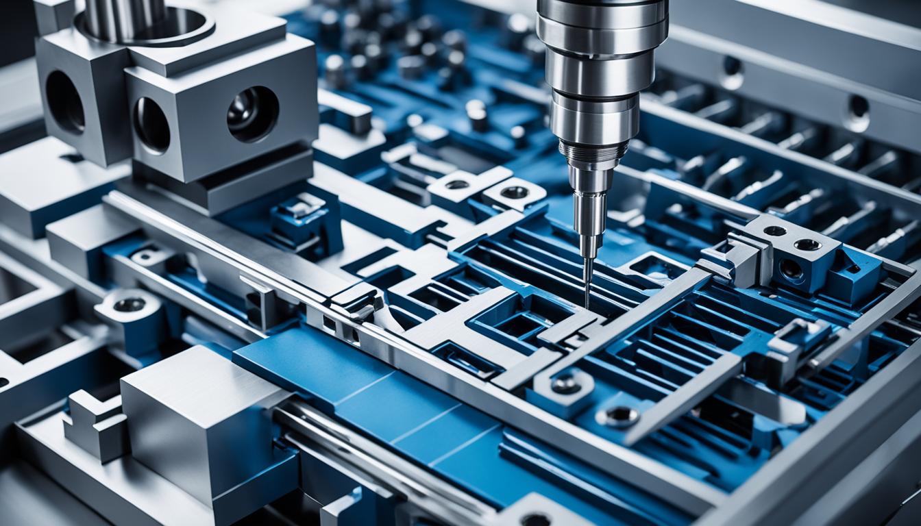
Modern manufacturing relies heavily on the synergistic integration of Computer-Aided Design (CAD), Computer-Aided Manufacturing (CAM), and Computer Numerical Control (CNC) technologies. These three pillars form the backbone of automated production, enabling unprecedented precision, efficiency, and complexity in part creation.
This integrated approach transforms digital models into physical components, streamlining the entire product development lifecycle. Engineers and machinists leverage these tools to design, simulate, program, and execute machining operations with remarkable accuracy and repeatability.
Computer-Aided Design: the Foundation
Computer-Aided Design (CAD) software serves as the initial stage in the digital manufacturing process, allowing engineers to create detailed 2D drawings and 3D models of parts and assemblies. These digital representations capture all geometric and material specifications necessary for production.
Current CAD platforms, such as SolidWorks, Autodesk Inventor, and CATIA, offer robust parametric modeling capabilities. This means design changes can be quickly propagated throughout the model, updating related features and assemblies automatically.
Advanced CAD systems also incorporate features like finite element analysis (FEA) for structural integrity checks and computational fluid dynamics (CFD) for performance simulations. These analytical tools help optimize designs for functionality and manufacturability before any physical prototyping begins.
Designers utilize various modeling techniques, including solid modeling, surface modeling, and direct modeling, to achieve complex geometries. The output is typically a neutral file format like STEP (.stp) or IGES (.igs), ensuring interoperability with other software.
Computer-Aided Manufacturing: Bridging Design to Production
| Parameter | CAD | CAM | CNC |
|---|---|---|---|
| Primary Function | Design & Modeling | Toolpath Generation | Machine Control |
| Input | Design Intent, Sketches | CAD Model (e.g., STEP, IGES) | G-code, M-code |
| Output | 3D Model, 2D Drawings | G-code, M-code Program | Finished Part |
| Key Software Examples | SolidWorks, Inventor, CATIA | Mastercam, Fusion 360, GibbsCAM | Fanuc, Siemens, Haas Controllers |
| Role in Workflow | Conceptualization | Process Planning | Physical Execution |
Computer-Aided Manufacturing (CAM) software translates the CAD model’s geometric data into machine-readable instructions, known as G-code and M-code, for CNC machines. This critical step defines the toolpaths, cutting parameters, and operational sequences.
CAM systems consider factors such as material type, cutting tool geometry, machine kinematics, and desired surface finish. They generate efficient and safe toolpaths for operations like milling, turning, drilling, and grinding.
Modern CAM software includes advanced features like multi-axis machining strategies, collision detection, and material removal simulation. These capabilities help optimize cycle times, extend tool life, and prevent costly errors during machining.
Feeds and speeds, crucial for effective machining, are calculated based on tool material, workpiece material, and cutting conditions. For example, milling 6061 aluminum with a 1/2′ carbide end mill might involve a surface speed of 800-1200 SFM and a chip load of 0.003-0.006 inches per tooth.
Computer Numerical Control: Precision Automation
Computer Numerical Control (CNC) refers to the automated control of machining tools by a computer. CNC machines interpret the G-code and M-code generated by CAM software to execute precise movements and operations.
These machines encompass a wide range of equipment, including CNC mills, lathes, routers, grinders, and even additive manufacturing systems. Each machine type is designed for specific manufacturing processes and part geometries.
CNC controllers, such as Fanuc, Siemens, Haas, and Heidenhain, act as the brain of the machine, processing the G-code instructions. They manage axis movements, spindle speeds, tool changes, and coolant flow with high accuracy.
Standard machining tolerances for CNC operations can be remarkably tight, often ranging from ±0.001 inches (±0.025 mm) for general machining to ±0.0002 inches (±0.005 mm) for high-precision applications, depending on the machine, material, and process.
The Digital Thread: Seamless Manufacturing Integration
The ‘digital thread’ represents a continuous, authoritative data stream that connects all stages of a product’s lifecycle, from initial design to manufacturing, inspection, and even field service. It ensures data integrity and traceability across disparate systems.
This integrated approach eliminates data silos and reduces errors associated with manual data transfer or re-entry. The digital thread facilitates real-time communication and collaboration among design, engineering, and production teams.
Key components of the digital thread include Product Lifecycle Management (PLM) systems, Manufacturing Execution Systems (MES), and Enterprise Resource Planning (ERP) software. These platforms manage data flow and process orchestration.
Implementing a robust digital thread workflow enhances efficiency, accelerates time-to-market, and improves overall product quality. It is a cornerstone of Industry 4.0 initiatives, driving smart manufacturing practices.
From Concept to Component: the Full Workflow
The journey from a conceptual idea to a finished physical part begins in the CAD environment. Here, engineers meticulously design the component, defining its geometry, dimensions, and material properties.
Once the CAD model is finalized and validated, it is imported into the CAM software. The CAM programmer then defines the machining operations, selects appropriate cutting tools, and generates optimized toolpaths.
The CAM system outputs the G-code and M-code program, which is then loaded into the CNC machine’s controller. The operator sets up the workpiece, fixtures, and tools according to the program’s requirements.
The CNC machine executes the program, precisely removing material to form the desired part. Throughout this process, quality control measures, often integrated with the digital thread, ensure the part meets all specified tolerances and surface finish requirements.