
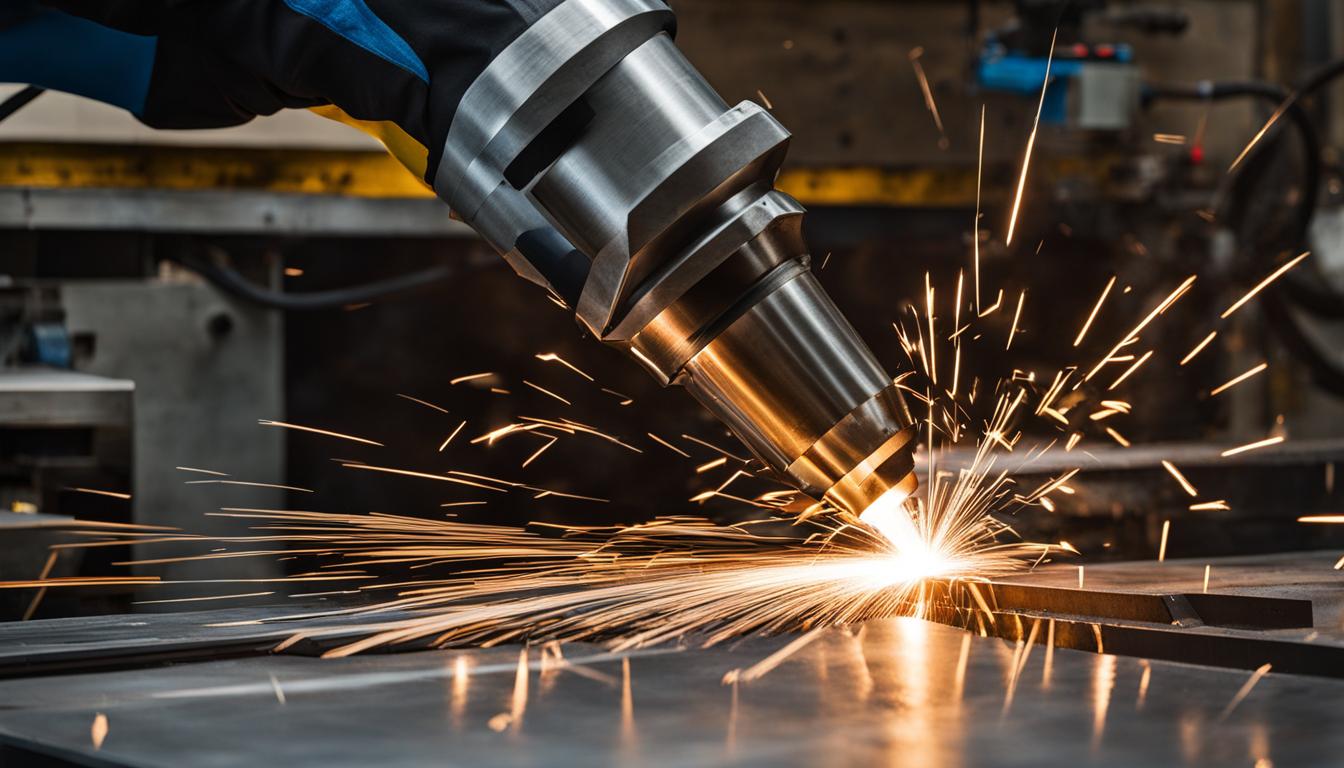
Constructing a DIY CNC plasma table offers significant cost savings and customization opportunities for metal fabrication enthusiasts. This guide details the essential technical aspects, from structural integrity to electronic integration, ensuring a robust and precise machine. Adhering to established engineering practices is paramount for both performance and safety.
Steel Tubing Frame Welding
The foundation of any reliable CNC plasma table is a rigid, precisely welded steel tubing frame. Square or rectangular steel tubing, typically 2×2 inch or 2×3 inch with a wall thickness of 0.120 to 0.188 inches, provides excellent torsional stiffness. Material selection often favors mild steel (e.g., A36 or 1018) for its weldability and cost-effectiveness.
Achieving dimensional accuracy during welding is critical to prevent binding in linear motion systems. Standard tolerances for as-welded frames, according to ISO 13920 Class B for linear dimensions and Class E for geometric form, suggest linear deviations of ±0.5mm to ±2.0mm and flatness of 0.3–0.8 mm per 300 mm. These tolerances are crucial for ensuring proper alignment of rails and gantry components.
MIG welding with ER70S-6 wire and a 75% Argon/25% CO2 shielding gas mixture is a common and effective method for joining steel tubing. Proper jigging and clamping are essential to minimize heat distortion, which is a significant challenge in welding. Employing a skip-welding sequence or intermittent welds can help distribute heat and reduce warpage.
Post-weld stress relief, though often impractical for DIY builds, can further enhance frame stability. For critical surfaces, machining after welding can achieve tighter flatness tolerances, typically 0.1–0.2 mm, which is beneficial for mounting linear rails.
Torch Height Control (THC) Installation
| Feature | Water Table | Downdraft Table |
|---|---|---|
| Fume Control | 80-95% (traps smoke, sparks, slag) | 70-90% (pulls fumes, fine particulates) |
| Material Warping | Reduced due to cooling | More common due to heat |
| Noise Level | Quieter (no fan noise) | Louder (requires fan/blower) |
| Maintenance | Water treatment, sludge removal | Filter changes, dust collector maintenance |
| Upfront Cost | Generally lower | Generally higher (fan, filters) |
| Aluminum Cutting | Not recommended (can create hydrogen gas) | Recommended (only viable option) |
Torch Height Control (THC) is an indispensable component for consistent plasma cutting quality, automatically maintaining the optimal distance between the torch and the workpiece. This system compensates for material warpage and unevenness, which are common in sheet metal.
Modern THC systems primarily utilize arc voltage sensing, where the plasma arc voltage (PAV) directly correlates to the torch-to-material distance. An integrated voltage divider card within the plasma power supply or an external voltage divider module, such as a 50:1 ratio unit, reduces the high arc voltage to a safe, usable range (e.g., 0-10V) for the CNC controller.
Initial setup involves installing the THC hardware, connecting sensors, and configuring the CNC software to communicate with the THC system. Ohmic sensing is frequently used for initial height sensing (IHS), detecting the material surface by electrical conductivity before the arc initiates. Proper grounding of the workpiece and plasma table is paramount to prevent EMI issues that can disrupt THC operation.
Calibration requires zeroing the torch to the material surface, setting initial voltage parameters based on the plasma cutter manufacturer’s recommendations, and performing test cuts. Fine-tuning the target voltage and anti-dive settings ensures optimal cut quality and prevents torch collisions, especially during corners or small hole cutting.
Water Bed vs. Downdraft Setup
Effective fume and slag management is crucial for operator health and shop cleanliness in plasma cutting. Two primary methods exist: water beds and downdraft tables. Each offers distinct advantages and disadvantages depending on the application and shop environment.
Water tables submerge the cutting surface in water, typically 2-24 inches deep, with the water level usually set just below the workpiece. This method effectively traps up to 90-95% of smoke, sparks, and slag, significantly reducing airborne particulates and noise. Water also cools the material, minimizing heat distortion and warpage, which can improve cut quality and allow for faster part handling.
Downdraft tables, conversely, use a fan or blower system to pull fumes and fine particulates downward through the cutting slats and into a filtration system or exhaust. These systems are generally cleaner to maintain, as there is no water to manage, and are the only option for cutting aluminum. Zoned downdraft tables, which activate suction only in the active cutting area, offer improved efficiency and reduced airflow requirements.
Choosing between the two involves considering factors like initial cost, maintenance, and the types of materials cut. Water tables are often less expensive upfront and require less energy, but demand regular water treatment and sludge removal. Downdraft systems have higher initial costs due to fans and filtration, and can increase utility bills by exhausting conditioned shop air, but offer superior air quality and easier slag removal.
Stepper Motor Drive Sizing
Selecting appropriately sized stepper motors and drives is crucial for achieving the desired speed, acceleration, and positional accuracy of a CNC plasma table. Stepper motors convert electrical pulses into precise mechanical movements, making them ideal for repeatable positioning in CNC applications.
Hybrid stepper motors are the most popular choice for CNC systems, combining the high torque of permanent magnet motors with the fine resolution of variable reluctance designs. They offer strong holding torque and accurate positioning, essential for maintaining gantry rigidity during cutting.
Motor sizing begins with calculating the required torque for each axis, considering factors like gantry weight, friction in linear bearings, and acceleration demands. NEMA frame sizes (e.g., NEMA 23, NEMA 34) indicate the motor’s faceplate dimensions and generally correlate with torque output. For typical DIY plasma tables, NEMA 23 motors are often sufficient for lighter gantries, while NEMA 34 motors provide greater power for larger or heavier setups.
Matching the stepper motor with a compatible driver is equally important. Drivers provide the necessary current and voltage to the motor windings, often employing microstepping to increase resolution and reduce vibration. Modern drivers offer features like current control, resonance suppression, and fault detection, enhancing system performance and reliability. Closed-loop stepper systems, which incorporate encoders, provide position feedback and can correct for missed steps, improving overall accuracy.
Plasma Cutter Wiring Setup
Properly wiring a plasma cutter to a CNC controller involves careful attention to safety, signal integrity, and electromagnetic interference (EMI) mitigation. The high-frequency start and cutting arc of a plasma system generate significant electrical noise that can disrupt sensitive control electronics.
A dedicated grounding scheme is essential, separating machine ground from control ground. This includes a supplemental ground rod installed within 20 feet (6 meters) of the table, connected to a common ‘star’ ground point on the cutting table with a minimum #6 AWG copper wire. All conductive components of the table, including the gantry and slats, must be robustly connected to this star ground.
Connecting the plasma cutter to the CNC controller typically involves two main signals: the ‘arc start’ signal and the ‘arc voltage’ signal for THC. The arc start signal, usually a dry contact closure from the CNC, triggers the plasma torch. The arc voltage signal, derived from the plasma cutter’s internal voltage divider or an external module, provides feedback to the THC system.
Shielded cables are highly recommended for all control signals to minimize EMI pickup. Running power and signal cables in separate cable tracks, maintaining at least 6 inches of separation, further reduces interference. Ensure all connections are secure and follow the plasma cutter and CNC controller manufacturer’s specific wiring diagrams for safe and reliable operation.