
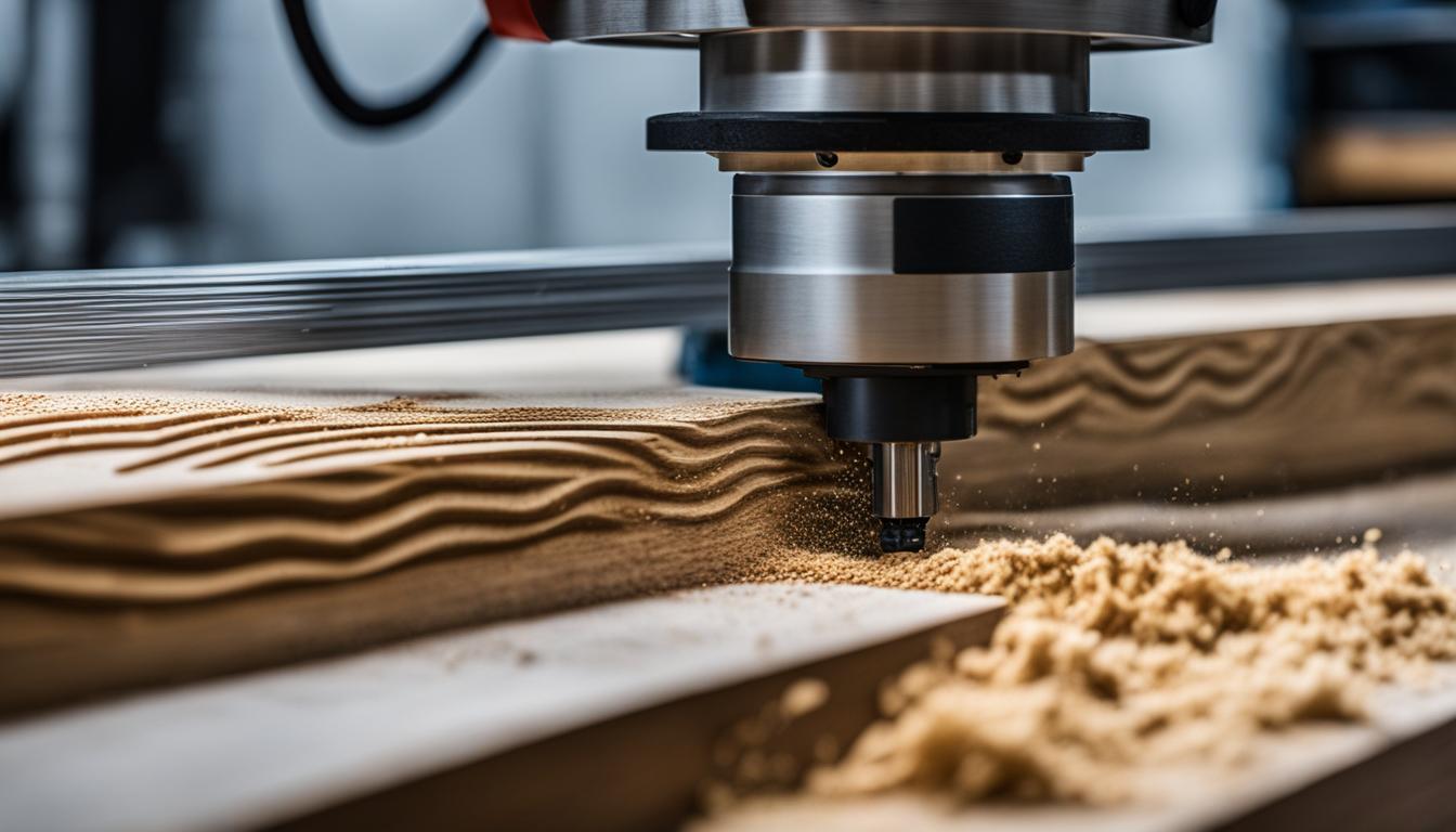
CNC routers provide precise material removal for various applications, from prototyping to production. These machines offer significant advantages over manual methods, delivering repeatability and accuracy essential for modern manufacturing. Understanding their core components and operational principles is fundamental for any aspiring or current operator.
A CNC router system integrates computer control with a robust mechanical structure to execute intricate cutting paths. This automation minimizes human error and maximizes efficiency, allowing for complex geometries and consistent part quality. The precision achievable with these machines makes them indispensable across numerous industries.
Flat Bed Gantry Systems
Flat bed router gantries form the structural backbone of most CNC routing operations. This design features a stationary bed where the workpiece is secured, while a movable gantry traverses over it, carrying the spindle and cutting tool. This configuration ensures stability and rigidity, crucial for maintaining machining accuracy.
Modern gantry systems often incorporate robust linear guides and ball screws, minimizing backlash and enhancing positional accuracy. The gantry’s movement along the X and Y axes, combined with the Z-axis movement of the spindle, enables three-dimensional machining. This design is particularly effective for processing large sheet materials like plywood or plastic panels.
Engineering practices for these gantries prioritize vibration dampening and structural integrity. Materials such as heavy-gauge steel or cast iron are commonly used for the machine frame to absorb cutting forces. Proper alignment and calibration of the gantry components are critical to achieving the standard tolerances of ±0.005 inches (±0.127 mm) for most linear dimensions in CNC machining. Precision work can achieve tighter tolerances, sometimes down to ±0.001 inches (±0.025 mm).
Material Processing: Wood and Plastics
| Bit Type | Chip Evacuation | Top Surface Finish | Bottom Surface Finish | Typical Applications |
|---|---|---|---|---|
| Upcut | Upward, efficient | Rougher (tear-out possible) | Clean, smooth | Deep grooves, mortises, pocketing, thicker materials |
| Downcut | Downward, less efficient | Clean, crisp | Rougher (tear-out possible) | Shallow grooves, dados, veneers, laminates, thin materials |
| Compression | Upward (bottom), Downward (top) | Clean | Clean | Through-cuts in sheet goods (e.g., plywood, MDF) |
CNC routers excel at machining a wide array of materials, with wood and plastics being among the most common. Each material type necessitates specific tooling, feeds, and speeds to achieve optimal results and prevent issues like melting or tear-out.
For woodworking, typical spindle speeds range from 16,000 to 24,000 RPM, depending on the bit size and wood hardness. Hardwoods generally require slower feed rates than softwoods to prevent burning and excessive tool wear. MDF, for instance, machines cleanly at 16,000-18,000 RPM with feed rates of 100-150 IPM, though its abrasive nature dulls tools faster.
Processing plastics demands careful attention to prevent melting and chip re-welding. Spindle speeds for plastics often fall between 12,000-16,000 RPM, with some recommendations for 18,000-24,000 RPM for acrylic. High feed rates are crucial to keep chips cool and evacuate them efficiently, preventing them from re-welding to the workpiece or tool. For soft plastics like HDPE, very sharp tools, high feed rates, and lower RPMs are recommended to avoid melting.
Router Bit Selection: Upcut and Downcut
Choosing the correct router bit is paramount for achieving desired surface finishes and efficient material removal. Upcut and downcut spiral bits are two primary types, each with distinct characteristics and applications.
Upcut spiral bits feature flutes that direct chips upward and out of the cut. This design provides efficient chip evacuation, allowing for faster cutting speeds and a cleaner bottom surface of the workpiece. However, upcut bits can cause fraying or tear-out on the top surface, especially with thinner or softer materials. They are ideal for deep grooves, mortises, and applications where a clean bottom edge is critical.
Conversely, downcut spiral bits have flutes that push chips downward into the cut. This action results in a very crisp and clean top edge, minimizing fraying and splintering, making them suitable for veneers, laminates, and shallow grooves. Downcut bits require slower feed rates due to less efficient chip evacuation, which can lead to chip buildup and overheating if run too fast. Compression bits, combining both upcut and downcut geometries, offer clean finishes on both top and bottom surfaces, particularly effective for through-cuts in sheet goods.
Vacuum Table Clamping
Vacuum table clamping systems are specialized workholding fixtures that significantly streamline the CNC machining process. They secure workpieces using atmospheric pressure, creating a strong hold-down force without traditional clamps. This method is particularly advantageous for flat, non-porous materials like plywood, MDF, and various plastics.
A vacuum table operates by creating a pressure differential: a vacuum pump removes air from beneath the workpiece, while atmospheric pressure pushes down from above. This differential generates substantial holding force; for example, a 10″ x 10″ part can experience nearly 1500 lbs of holding force at sea level with a sufficient vacuum. The system typically includes a vacuum pump, a plenum (the work surface), and a piping system. An optional bleeder board, often porous MDF, helps spread the vacuum and protects the plenum from tool damage.
Benefits of vacuum clamping include rapid workpiece changes, full access to the workpiece edges, and reduced tool chatter, which improves edge quality. Various types exist, including grid-like tables with evenly spaced holes, porous tables for delicate materials, and zoned systems that allow vacuum application to specific areas. These systems are available for both industrial and smaller, home workshop CNC routers.
Basic G-Code Software
G-code, or ‘Geometric Code,’ is the fundamental programming language that instructs CNC machines on precise movements and operations. It translates digital designs into physical toolpaths, dictating where the tool starts, stops, its path, and its speed. Understanding basic G-code is essential for anyone involved in CNC machining, even if CAM software automates much of the process.
Common G-code commands include G00 for rapid positioning (non-cutting moves) and G01 for linear cutting movements at a specified feed rate. G02 and G03 commands control circular interpolation for clockwise and counter-clockwise arcs, respectively. Other critical commands include G20/G21 for setting units to inches or millimeters, and G90/G91 for absolute or incremental positioning.
Numerous software options assist beginners in generating and understanding G-code. CAD (Computer-Aided Design) software is used to create the part design, while CAM (Computer-Aided Manufacturing) software translates this design into toolpaths and then generates the G-code. Popular beginner-friendly CAM software includes Easel, which offers an intuitive browser-based interface and can generate G-code without requiring manual programming. Carbide Create is another free 2D CAM software that can produce G-code for various CNC routers. For those seeking more advanced capabilities, Fusion 360 integrates CAD and CAM functionalities, providing comprehensive tools for design and G-code generation.