
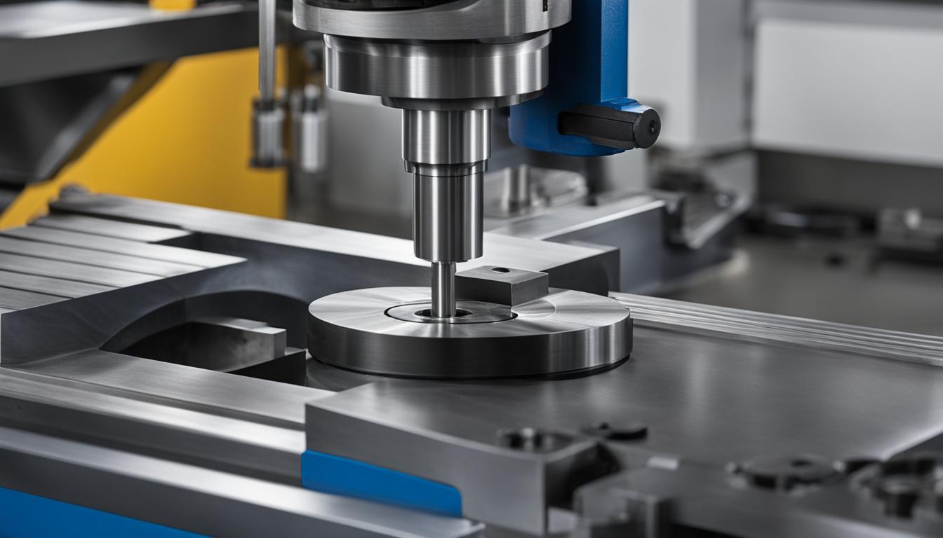
Precision manufacturing relies heavily on subtractive processes like turning and milling to achieve desired part geometries. While both methods remove material to shape a workpiece, their fundamental kinematics, tooling, and resulting part features differ significantly. Understanding these distinctions is crucial for selecting the optimal machining strategy for any given component.
Each process offers unique advantages, making them indispensable in modern workshops. The choice between turning and milling often dictates the efficiency, accuracy, and surface finish of the final product.
Fundamental Kinematics: Part vs. Cutter Motion
Turning operations fundamentally involve a rotating workpiece and a stationary or linearly moving cutting tool. The primary motion is the workpiece’s rotation around its axis, while the cutting tool performs the feed motion, typically along the X and Z axes to control diameter and length respectively.
Conversely, milling processes operate with a rotating cutting tool and a workpiece that remains largely stationary or moves linearly along multiple axes. The cutting tool, often an end mill or face mill, rotates at high speed, while the workpiece is fed into the cutter in X, Y, and Z directions.
This difference in primary motion dictates how material is removed and chips are formed. Turning typically results in continuous chip formation as the single-point tool maintains constant contact with the rotating part. Milling, utilizing multi-point rotary tools, often involves ‘interrupted cutting’ where each tooth engages and disengages from the workpiece, influencing chip load and cutting forces.
Machine Operations: Lathes and Mills
| Feature | CNC Turning | CNC Milling |
|---|---|---|
| Workpiece Motion | Rotates | Stationary or Linear Feed |
| Cutter Motion | Stationary or Linear Feed | Rotates |
| Primary Geometry | Cylindrical, Conical, Spherical | Planar, Pockets, Slots, Contours |
| Typical Tooling | Single-point cutting tools (inserts) | Multi-point rotary tools (end mills, face mills) |
| Standard Tolerance | ±0.005″ (±0.127 mm) | ±0.005″ (±0.127 mm) |
| Typical Surface Finish (Ra) | 1.6 – 6.3 μm (63 – 250 μin) | 0.4 – 12.5 μm (16 – 500 μin) |
Lathes are the primary machines for turning operations, designed to hold and rotate a workpiece about a fixed axis. Workholding devices like chucks or collets secure the material, which then spins while a single-point cutting tool removes material from its exterior or interior.
Milling machines, on the other hand, secure the workpiece to a stationary table, allowing a rotating multi-point cutter to move across or into the material. These machines typically offer movement along at least three axes (X, Y, Z), enabling complex contouring and pocketing.
Modern CNC lathes, especially those with ‘live tooling’ capabilities, can perform some milling operations by rotating the cutting tool while the workpiece is held stationary or indexed. Similarly, advanced multi-axis milling machines can interpolate circular features, blurring the traditional lines between the two processes.
Geometric Outcomes: Cylindrical vs. Planar Features
Turning is inherently suited for producing parts with rotational symmetry. Operations like straight turning, facing, boring, grooving, and threading create cylindrical, conical, or spherical shapes. Components such as shafts, pins, bushings, and hydraulic fittings are classic examples of turned parts.
Milling excels at creating non-rotationally symmetric features, including flat surfaces, slots, pockets, grooves, and intricate contours. It is the go-to process for machining rectangular valve bodies, electronic housings, and complex structural brackets.
Pocket milling, a common milling operation, removes material from within a defined boundary to create recessed cavities. This process is critical for parts requiring internal features, weight reduction, or specific mounting areas.
Tooling Distinctions: Single Point vs. Rotary Bit
Turning primarily employs single-point cutting tools, characterized by a single sharp cutting edge in contact with the workpiece. These tools, often indexable carbide inserts mounted in tool holders, feature specific geometries like rake angles, relief angles, and a nose radius that significantly influence surface finish and tool strength.
Milling machines utilize rotary cutting tools, such as end mills, face mills, and drills, which possess multiple cutting edges. These tools rotate to remove material, with their geometry (e.g., number of flutes, helix angle, coating) optimized for specific materials and operations.
The choice of tool material, such as high-speed steel (HSS) or carbide, and specialized coatings like ZrN or DLC, is critical for both processes. These selections impact tool life, heat resistance, and the ability to prevent built-up edge, especially when machining materials like aluminum.
Process Parameters and Modern Practices
Optimizing feeds and speeds is paramount for efficient machining in both turning and milling. For CNC turning, parameters include spindle RPM, feed rate (inches per revolution or mm per revolution), and depth of cut. These factors directly affect material removal rate, tool wear, and surface finish.
In CNC milling, critical parameters include spindle RPM, feed rate (inches per minute or mm per minute), chip load per tooth, and axial/radial depth of cut. For aluminum, typical milling RPM can range from 6,000 to 20,000 RPM, with feed rates of 40-80 IPM for a 2-flute end mill, depending on the alloy and machine rigidity.
Modern engineering practices leverage advanced CAM software for toolpath optimization, such as adaptive clearing in milling, which maintains a constant tool engagement angle for higher feed rates. High-speed machining (HSM) is also prevalent, utilizing high RPM and lighter cuts for improved efficiency and surface quality.
Standard tolerances for CNC machining typically fall around ±0.005 inches (±0.127 mm) for most metals. Precision machining can achieve tighter tolerances, often ±0.001 to ±0.002 inches (±0.0254 to ±0.0508 mm), with specialized techniques reaching 1-5 microns for critical applications in aerospace and medical industries.
Surface finish, commonly measured as Ra (Roughness Average), is also a key consideration. Standard as-machined surfaces typically have an Ra of 3.2 μm (125 μin) for both milling and turning. Finer finishes, down to Ra 0.4-0.8 μm, can be achieved with additional finishing passes or secondary operations, though this increases cost.