
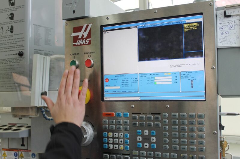
Skilled CNC technicians are indispensable for maintaining the operational integrity and precision of advanced manufacturing equipment. Their multifaceted role encompasses a broad spectrum of technical duties, ensuring machines operate efficiently and safely. These professionals are critical in minimizing downtime and upholding production quality across various industries.
A CNC machine repair technician’s tasks typically involve diagnosing and resolving both mechanical and electrical issues, performing routine maintenance, and calibrating equipment. They often work closely with machine operators and engineers to keep production lines running smoothly.
Electrical and Mechanical Repairs
Addressing electrical and mechanical malfunctions is a core responsibility for CNC technicians. Electrical issues can range from simple blown fuses to complex controller malfunctions, often stemming from faulty wiring, overloaded circuits, or motor failures. Technicians must systematically diagnose these problems, adhering strictly to safety protocols.
Common electrical problems include complete power failure, controller alarms, servo drive faults, and intermittent sensor signals. Technicians utilize multimeters to verify power input and inspect electrical cabinets for loose connections, dust accumulation, or signs of overheating. Proper grounding is also crucial to prevent electrical interference.
Mechanical repairs frequently involve components like ball screws, linear guides, and spindles. Backlash, a common mechanical issue, manifests as lost motion during axis direction changes, compromising positioning accuracy. Technicians diagnose backlash using dial indicators and may perform mechanical adjustments such as tightening bearing nuts or replacing worn ball screw components.
Inspecting and maintaining lubrication lines, checking spindle belt tension, and tightening accessible fasteners are also routine mechanical tasks. These actions prevent premature wear and ensure the smooth operation of moving parts.
Machine Calibration Procedures
| Tolerance Type | Standard Range (mm) | High-Precision Range (mm) |
|---|---|---|
| Linear Dimensions | ±0.125 mm (±0.005 in) | ±0.01 mm (±0.0004 in) |
| Angular Tolerances | ±0.5° | ±0.25° |
| Spindle Runout (New VMC) | ≤25 µm (0.001 in) | ≤10 µm (0.0004 in) |
| Ball Screw Backlash | 0.01–0.02 mm (0.0004–0.0008 in) | <0.01 mm (0.0004 in) |
Regular machine calibration is essential to guarantee that CNC machines hold specified tolerances and produce accurate parts. Calibration involves checking and adjusting machine settings against established accuracy standards.
International standards like ISO 230-2 govern the determination of accuracy and repeatability of positioning for numerically controlled axes. These standards outline test procedures, including warm-up cycles, target positions, and the number of approaches for measurement.
Technicians use precision tools like laser interferometers, ball bars, and dial indicators to measure geometric accuracy, parallelism, perpendicularity, and backlash. Backlash values, for instance, are measured with a dial indicator mounted against the worktable, with acceptable residual backlash typically between 0.01–0.02 mm.
After mechanical adjustments, backlash compensation values can be entered into the CNC controller. This software compensation adds extra rotation during direction reversals to mask mechanical backlash, improving repeatability. However, it does not eliminate the physical gap.
Preventive Maintenance Schedules
Implementing a structured preventive maintenance (PM) schedule is fundamental for extending machine life and ensuring consistent part quality. PM routines are typically categorized into daily, weekly, monthly, quarterly, and annual tasks, with intervals adjusted based on production intensity and manufacturer recommendations.
Daily tasks often include cleaning the work area, inspecting cutting tools, verifying lubrication, and performing quick visual inspections for loose fasteners or damaged cables. Removing chips and debris prevents coolant retention and rust formation.
Weekly maintenance involves cleaning motion components like linear rails and guideways, inspecting belts and couplings for wear, and checking coolant or dust collection systems. Spindle taper inspection is also a weekly task.
Monthly tasks expand to include inspecting electrical cabinet ventilation, checking machine alignment indicators, reviewing maintenance logs, and inspecting hydraulic system components. Backlash measurement is also a critical monthly check.
Less frequent, but equally important, quarterly or semi-annual maintenance involves checking machine leveling, draining and replacing oils, cleaning coolant tanks, and inspecting way wipers. Annual inspections often require professional calibration, bearing inspection, and geometric accuracy verification.
Troubleshooting Error Codes
CNC machines utilize sophisticated control systems that generate error codes to indicate malfunctions. Understanding these codes is paramount for rapid diagnosis and minimizing downtime. Common control systems like Fanuc, Haas, and Siemens have distinct alarm categories.
Error codes are typically classified into servo alarms (axis or motor-related), spindle alarms (spindle or drive issues), overtravel/safety alarms (mechanical or limit switch triggers), program alarms (syntax or logic errors), and communication alarms. Each category points to a specific area of the machine requiring attention.
When an alarm occurs, technicians first identify the specific code displayed on the controller screen or in the alarm history. They then consult manufacturer manuals to understand the alarm’s meaning and common causes.
Troubleshooting steps involve verifying power input, inspecting electrical components for damage, checking mechanical parts for wear, and reviewing the CNC program for errors. Many modern CNCs also offer diagnostic software that provides real-time data on axis load, following error, and signal states.
A recurring alarm often signals an unresolved mechanical or electrical issue, such as a degrading bearing or an intermittent cable. Technicians must address the root cause, not just reset the alarm, to prevent its immediate return.
Spindle Realignments
Maintaining precise spindle alignment is critical for achieving high-quality surface finishes and accurate part dimensions. Spindle runout, a key indicator of alignment, refers to the fluctuation of a feature relative to a datum when the part rotates 360 degrees.
New precision vertical machining centers (VMCs) should exhibit radial runout of ≤10 µm (0.0004 inches), while standard machines typically allow up to 25 µm (0.001 inches). Excessive runout, such as 0.008 inches, is considered highly problematic and can lead to vibration and rapid bearing wear.
Measuring spindle runout involves mounting a precision dial test indicator (DTI) with 0.0001-inch resolution on a test bar inserted into the spindle. The DTI is positioned near the spindle face, and the spindle is rotated by hand to record the total indicator reading (TIR).
If runout exceeds acceptable limits, technicians investigate potential causes such as bearing condition, spindle housing alignment, taper wear, or drawbar force. Prussian blue can be used to inspect the contact pattern of dual-contact spindle tapers, revealing issues like ‘bell-mouth’ wear.
Spindle realignments may involve adjusting bearing preload, shimming the spindle cartridge to achieve concentricity with the machine table, or, in severe cases, replacing worn bearings or a bent spindle. These precise adjustments restore the spindle’s rotational accuracy.