
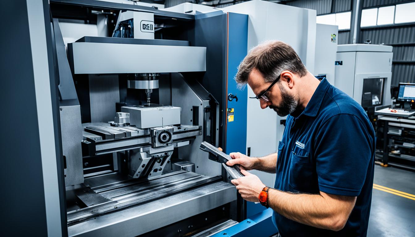
Computer Numerical Control (CNC) machining relies on precisely controlled axes of motion to shape raw materials into finished components. The number of axes a machine possesses directly dictates its capabilities, influencing part complexity, achievable tolerances, and overall manufacturing efficiency. Understanding these distinctions is fundamental for selecting the optimal machine for any given production requirement.
CNC machines are broadly categorized by their number of controlled axes: 3-axis, 4-axis, and 5-axis. Each configuration offers a unique balance of flexibility, precision, and operational complexity. The choice significantly impacts design freedom, setup times, and the final quality of machined parts.
Linear Axis Motion Limits
Three-axis CNC machines operate along three linear axes: X (left-right), Y (front-back), and Z (up-down). The cutting tool moves across these perpendicular directions while the workpiece remains stationary on the machine table. This setup is ideal for machining flat surfaces, simple contours, and basic geometric shapes.
Typical linear axis travel limits vary widely by machine size and type, but for a standard 3-axis mill, the Z-axis travel, which dictates cutting depth, is often around 600 mm (23.6 inches). The work envelope for X and Y axes also defines the maximum part size that can be machined without repositioning.
These machines excel at tasks like cutting, drilling, and milling simple prismatic components. However, their limitations become apparent when parts require features with complex curves, undercuts, or non-perpendicular angles, as the tool cannot tilt or rotate relative to the workpiece.
Rotational Rotary Axis Addition
| Feature | 3-Axis CNC | 4-Axis CNC | 5-Axis CNC |
|---|---|---|---|
| Axes of Motion | X, Y, Z (3 linear) | X, Y, Z + 1 rotary (A or B) | X, Y, Z + 2 rotary (A/C or B/C) |
| Workpiece Setup | Multiple setups often required | Fewer setups, multi-sided access | Single setup for complex parts |
| Geometric Complexity | Simple, prismatic parts, 2.5D features | Cylindrical, multi-face, angled features, helical | Complex 3D contours, undercuts, organic shapes |
| Tool Access | Limited, fixed tool orientation | Improved via workpiece rotation | Optimal, tool/part tilt and rotation |
| Programming Complexity | Simplest, basic G-code | Moderate, advanced CAM for continuous | Highest, sophisticated CAM, simulation |
| Typical Linear Tolerances | ±0.125 mm (±0.005 in) | ±0.025 mm (±0.001 in) to ±0.05 mm (±0.002 in) | ±0.012 mm (±0.0005 in) or better, down to 1-3 microns |
| Common Applications | Flat plates, simple brackets, panels, molds | Shafts, valve bodies, engine blocks, aerospace parts | Turbine blades, impellers, medical implants, aerospace components |
Four-axis CNC machining introduces a single rotary axis, typically designated as the A-axis, which rotates around the X-axis. This additional degree of freedom allows the workpiece to rotate during or between cutting operations, exposing multiple faces or cylindrical surfaces without manual repositioning.
This rotary axis can operate in two primary modes: indexed (3+1) or continuous. In indexed machining, the workpiece rotates to a specific angle and locks in place before the machine performs standard 3-axis operations. Continuous 4-axis machining involves the synchronized movement of the rotary axis and linear axes during the cutting process, enabling the creation of complex features like helical grooves or cams.
Five-axis CNC machines further enhance capabilities by adding a second rotational axis, providing even greater degrees of freedom. These machines combine the three linear axes (X, Y, Z) with two rotational axes (A/C or B/C). The rotational axes can be configured in various ways, such as a rotary table mounted on a tilting table, or a tilting spindle head.
Common 5-axis kinematic configurations include ‘table-table’ where both rotary axes are in the workpiece table, or ‘head-head’ where both rotary axes are in the spindle head. Another configuration is ‘head-table,’ where one rotary axis is in the head and the other in the table. These configurations allow the tool to approach the workpiece from virtually any angle.
Single Setup Complex Cuts
The ability to perform complex cuts in a single setup is a significant advantage of multi-axis machines. Three-axis machines often require multiple manual repositioning of the workpiece to access different sides, increasing labor costs and the risk of human error in alignment. Each setup introduces potential accuracy variations and extends overall cycle times.
Four-axis machines significantly reduce the need for multiple setups for multi-sided parts. By rotating the workpiece within the same fixture, the machine maintains a common datum, improving positional accuracy between features on different faces. This streamlines production for parts requiring features on multiple sides, circular features, or specific angular relationships.
Five-axis machining excels in single-setup capabilities, allowing the creation of intricate features, deep cavities, and complex contours in one continuous operation. This eliminates the need for multiple setups and re-fixturing, which drastically reduces setup time and improves precision by maintaining a single coordinate system throughout the entire machining process.
Tool Access Orientation
Tool access is a critical limitation for 3-axis machines. The fixed orientation of the spindle means the cutting tool can only approach the workpiece from a single direction (typically perpendicular to the table). This makes it challenging to reach deep cavities, narrow internal features, or machine undercuts without manually repositioning the part.
Four-axis machines improve tool access by rotating the workpiece, allowing the tool to reach side holes, radial slots, circumferential grooves, and angled faces. This capability often reduces the need for longer tools that may compromise rigidity and cutting performance.
Five-axis machines offer unparalleled tool access, as the cutting tool can tilt and rotate to approach the workpiece from virtually any angle. This enables the use of shorter, more rigid tools, which reduces chatter, improves surface finish, and extends tool life. It also allows for machining complex angles and shapes that would be impossible with fewer axes.
Programming Complexity Scale
Programming complexity scales significantly with the addition of more axes. Three-axis machines are the simplest to program, typically using basic G-code for linear motions. The learning curve for operators is shorter, and maintenance is generally easier.
Four-axis programming requires more advanced CAM software, especially for continuous rotation operations where the toolpath must account for constant rotational motion. Indexed 4-axis machining is somewhat simpler, involving rotation to a fixed angle before 3-axis cutting.
Five-axis programming is the most complex, demanding highly skilled machinists, sophisticated CAM software, and extensive simulation for toolpath verification and collision checking. Understanding machine kinematics, tool center point control, and tilted working planes is crucial. The learning curve for experienced CNC programmers can range from 6-12 months.