
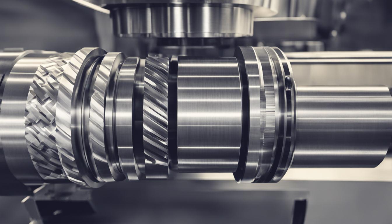
Turning is a subtractive manufacturing process that precisely shapes a workpiece by removing material. This method primarily creates cylindrical, conical, or other rotationally symmetric surfaces on various materials, including metals, plastics, wood, and stone.
The core principle involves a rotating workpiece and a stationary, single-point cutting tool. This tool moves relative to the workpiece, shaving off excess material to achieve the desired form and dimensions.
Fundamentals of Lathe Turning
Lathe machines are the primary equipment for turning operations, capable of performing diverse tasks like threading, boring, and facing. These versatile machines facilitate the removal of unneeded material as the workpiece spins along its axis.
The process typically begins with a workpiece generated from other methods, such as casting, forging, extrusion, or drawing. Turning then refines these initial forms into final components, often with high precision.
Workpiece Clamping and Rotational Dynamics
| Material | Tooling | Cutting Speed (SFM / m/min) | Feed Rate (IPR / mm/rev) | Depth of Cut (DOC) |
|---|---|---|---|---|
| Aluminum (6061/3003) | Carbide | 600-1200 SFM (180-365 m/min) | 0.004-0.010 IPR (roughing) | Shallow to moderate |
| Mild Steel | Carbide | 80-150 m/min | 0.10-0.30 mm/rev (roughing) | 2-6 mm (roughing) |
| General Purpose | HSS | ~400 SFM (120 m/min) | 0.001-0.005 IPR (parting) | Light cuts |
Securely holding the workpiece is paramount in turning to ensure accuracy, rigidity, and safety. The chosen workholding method directly influences the quality of the finished product and the machinist’s safety.
Chucks are the most common workholding devices, mounted directly to the lathe spindle. Three-jaw self-centering chucks are ideal for quickly setting up round or hexagonal stock, automatically centering the workpiece.
For irregularly shaped components or when higher precision is needed, four-jaw independent chucks offer individual jaw adjustment. Soft jaws, bored and faced to suit specific workpiece dimensions, are often used for finishing operations to prevent marring previously machined surfaces.
Longer workpieces may require additional support from a steady rest, clamped to the lathe bed, or by being held ‘between centers’ using a drive center in the headstock and a live or dead center in the tailstock.
Single-Point Tooling and Material Reduction
Turning operations predominantly utilize single-point cutting tools, meaning only one cutting edge engages the workpiece at a time. These tools consist of a sharpened cutting part and a shank, performing various operations like turning and facing.
The tool’s geometry, including rake angle, clearance angle, and nose radius, critically influences chip formation, heat distribution, and surface finish. A larger nose radius, for instance, generally produces smoother surfaces.
Material reduction to a desired diameter occurs as the cutting tool moves parallel to the workpiece’s axis of rotation. This axial movement, combined with radial depth of cut, progressively removes material from the external surface.
Rough turning aims to remove the maximum amount of material quickly, prioritizing volume over surface finish and accuracy. Subsequent finish turning operations then achieve the final accurate dimensions and a smooth surface finish.
Specialized Turning Operations: Facing, Threading, and Boring
Facing is a machining operation that reduces the workpiece length and creates a flat, smooth end surface. The cutting tool moves perpendicular to the axis of rotation, typically from the outer edge towards the center.
Threading involves cutting helical grooves onto the outer or inner surface of a workpiece, forming threads with specified pitches and lengths. This requires a thread-shaped cutting tool bit and precise, synchronized movement of the tool along the workpiece.
Boring is the process of enlarging an existing hole or creating specified internal shapes within a workpiece. A single-point cutting tool enters the workpiece axially, removing material from the internal surface.
Mechanics of Chip Formation
Chip formation is a complex phenomenon involving the plastic deformation and subsequent detachment of material from the workpiece. This process occurs in a ‘primary deformation zone’ where high pressure and temperature are generated.
The material undergoes significant plastic deformation and shearing in this zone, with mechanical energy largely converted into heat due to friction and stress. The plastic flow angle, influenced by cutting speed and tool geometry, dictates the chip formation mode.
Chips are generally categorized into continuous, discontinuous, and segmented types. Continuous chips form from ductile materials at high cutting speeds and low feed rates, often coiling into spirals.
Discontinuous chips result from machining harder or brittle materials, or at high feed rates, appearing as separate elements. Proper chip formation and evacuation are crucial for an undisturbed cutting process, ensuring operator safety and preventing damage to the machine, tool, and workpiece.
Modern Parameters and Precision Tolerances
Modern CNC turning centers achieve tight tolerances and high repeatability, essential for complex geometries and high-volume production. Standard machining tolerances can be as tight as ±0.13 mm, with precision machining reaching ±0.051 mm.
ISO 2768-1 defines general tolerances for linear and angular dimensions when specific tolerances are not explicitly stated on a drawing. It includes four tolerance classes: ‘f’ (fine), ‘m’ (medium), ‘c’ (coarse), and ‘v’ (very coarse), with ‘m’ being the common general-purpose default.
For features requiring precise fits, such as shafts and holes, the ISO 286 standard specifies tolerance classes like IT6, IT7, and IT8. Specifying the appropriate tolerance class, such as ‘ISO 2768-m’, in the drawing’s title block is standard practice.
Feeds and speeds are critical parameters, with cutting speed (Vc) defining how fast the workpiece surface passes the cutting edge, and feed rate (f) indicating the tool’s advance per revolution. These values are material and tool-dependent.
For roughing operations, higher feed rates (0.25–0.5 mm/rev) and deeper cuts are employed to remove material rapidly. Finishing passes utilize lower feed rates (0.05–0.15 mm/rev) to achieve superior surface finish and meet tight tolerances.
When starting a new operation, it is a best practice to begin with 70–85% of recommended feed and speed values. This conservative approach helps ensure insert and machine stability, allowing for adjustments as performance is evaluated.