
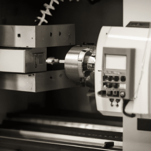
Computer Numerical Control (CNC) machine tools represent the backbone of modern manufacturing, enabling high-precision and repeatable production across diverse industries. Understanding the core components of these sophisticated machines is fundamental for engineers, machinists, and anyone involved in advanced manufacturing processes. Each element plays a critical role in the machine’s overall performance, accuracy, and reliability.
The integration of these components allows for automated, multi-axis motion and complex material removal operations. From the human-machine interface to the robust structural elements and dynamic motion systems, every part is engineered for optimal interaction and performance. This technical overview delves into the primary constituents that define a CNC machine tool’s capabilities.
CNC Controller Panel
The CNC controller panel serves as the brain of the machine, translating G-code and M-code instructions into precise mechanical movements. Modern controllers feature advanced Human-Machine Interfaces (HMIs) with intuitive touchscreens and graphical displays, enhancing operator interaction and programming efficiency. These systems often incorporate powerful processors to handle complex interpolation and look-ahead algorithms, crucial for high-speed and multi-axis machining.
Leading manufacturers like Fanuc, Siemens, and Haas offer controllers with varying levels of sophistication, from entry-level systems to highly integrated platforms supporting Industry 4.0 initiatives. These controllers manage servo drives, spindle speeds, tool changes, and safety interlocks, ensuring synchronized operation. Communication protocols are typically standardized, allowing for seamless data exchange within a manufacturing environment.
Current CNC controllers boast enhanced diagnostic capabilities and real-time monitoring, providing operators with immediate feedback on machine status and performance. Integrated simulation software allows for program verification before actual machining, minimizing errors and material waste. Advanced features include adaptive control, which adjusts feeds and speeds based on real-time cutting conditions, optimizing tool life and surface finish.
Machine Bed and Column
| Parameter | High-Speed Spindle | High-Torque Spindle |
|---|---|---|
| Power Output | 4 kW – 6 kW (air-cooled), 5 kW – 10 kW (water-cooled) | 10 kW+ (water-cooled) |
| RPM Range | 20,000 – 60,000 RPM (some up to 250,000 RPM) | 5,000 – 15,000 RPM |
| Cooling System | Air-cooled or Water-cooled | Water-cooled |
| Bearing Type | Ceramic Hybrid Angular Contact Ball Bearings | Angular Contact Ball Bearings, Cylindrical Roller Bearings |
| Tool Taper | HSK (e.g., HSK-A63, HSK-E40) | CAT (e.g., CAT40, CAT50), BT (e.g., BT40, BT50) |
The machine bed and column form the foundational structure of a CNC machine tool, providing the rigidity and stability essential for precision machining. These components are typically constructed from high-grade cast iron, renowned for its excellent vibration damping characteristics and thermal stability. Modern designs often incorporate finite element analysis (FEA) to optimize material distribution, maximizing stiffness while minimizing weight.
Maintaining geometric accuracy, such as flatness and perpendicularity, across these structures is paramount. Standard flatness tolerances for machine beds are extremely tight, often measured in micrometers over the entire working surface, to ensure consistent machining accuracy.
Advanced CNC machines may utilize composite materials or specialized concrete fills within the cast iron structure to further enhance vibration absorption and thermal stability. These materials help mitigate the effects of heat generated during prolonged machining operations, which can otherwise lead to thermal expansion and dimensional inaccuracies. The overall mass and structural integrity directly influence the machine’s ability to withstand cutting forces without deflection.
Spindle Motor Drive
The spindle motor drive is responsible for rotating the cutting tool at precise speeds and delivering the necessary torque for material removal. Modern CNC machines employ various spindle motor types, including belt-driven, gear-driven, and direct-drive systems, each offering distinct advantages in terms of speed, torque, and precision. Direct-drive spindles, where the motor rotor is integrated directly onto the spindle shaft, are increasingly common in high-speed applications due to their minimal vibration and excellent rotational accuracy.
Spindle power ratings are critical, with continuous (S1 duty) and time-limited (S6 duty) ratings indicating the motor’s sustained and peak performance capabilities, respectively. For most small to medium CNC machines, motors in the 1.5 kW to 3 kW range are common, while industrial operations may utilize 5 kW to 10 kW or even higher power units. High-speed spindles can achieve rotational speeds from 20,000 RPM to 60,000 RPM, with some specialized units reaching up to 250,000 RPM for micro-machining.
Precision spindle bearings are vital for maintaining accuracy and stability at high RPMs. Angular contact ball bearings are widely used, designed to handle both radial and axial loads, often mounted in matched pairs for increased stiffness. Ceramic hybrid bearings, featuring ceramic rollers and steel rings, offer superior heat resistance, lower friction, and extended service life, making them ideal for high-precision, high-speed applications. Effective cooling systems, such as water or air cooling, are essential to manage heat generated during operation, preventing thermal expansion and premature bearing failure.
Ball Screws and Guides
Ball screws and linear guides are fundamental for precise and repeatable linear motion along the machine axes. Ball screws convert rotary motion from servo motors into linear motion with high efficiency and minimal friction, utilizing recirculating ball bearings between the screw shaft and the nut. Precision-ground ball screws are available in various accuracy classes, such as C3 or C5, offering minimal inherent backlash for demanding applications.
Linear guides, also known as linear guide rails, provide the pathway for axis movement, supporting the load and ensuring smooth, stable, and accurate linear motion. Ball linear rails offer low friction and high speed, suitable for automation and small to medium CNC machines, while roller linear guides provide significantly higher load capacity and rigidity, ideal for heavy cutting and gantry machine tools.
Preload is a critical aspect of linear guide and ball screw performance, eliminating internal clearance and increasing rigidity to reduce deflection under external loads. Various preload classes (e.g., Z0, ZA, ZB for linear guides; K0, K1, K2 for profile-rail guides) are selected based on application requirements, balancing rigidity with friction, heat generation, and service life. Backlash compensation, either mechanical (e.g., preloaded ball nuts, double-nut systems) or software-based (using linear scales), is essential to maintain positional accuracy, especially during direction reversals.
Automatic Tool Changer (ATC)
The Automatic Tool Changer (ATC) is a critical system that significantly enhances CNC machine productivity by automating tool changes without operator intervention. This capability reduces cycle times by 30-50%, enables ‘lights-out’ manufacturing, and improves overall efficiency. An ATC system typically comprises a tool magazine, a tool change arm mechanism, and a control system.
Tool magazines store a variety of cutting tools in standardized holders, such as BT, CAT, DIN, or HSK tapers. When the CNC program commands a tool change, the control system directs the magazine to present the correct tool. A dual-gripper arm then simultaneously removes the current tool from the spindle and inserts the new one, completing the exchange within seconds.
Modern ATC systems utilize servo motors for precise magazine positioning and hydraulic or pneumatic clamping mechanisms to secure tools in both the magazine and the spindle. This ensures accurate tool selection and prevents movement during high-speed machining operations. The integration of tool identification systems further streamlines the process, verifying that the correct tool is installed and secured before machining resumes.