
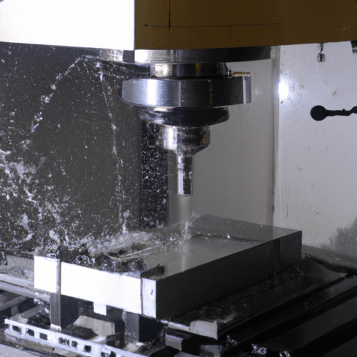
Milling operations form the bedrock of subtractive manufacturing, enabling the precise shaping of raw materials into functional components. Two fundamental categories, peripheral milling and face milling, define distinct approaches to material removal, each with unique characteristics influencing surface finish, material removal rates, and overall part geometry.
Selecting the appropriate milling strategy is critical for optimizing machining efficiency and achieving desired part specifications. This choice hinges on understanding the mechanics of how the cutting tool engages the workpiece, the direction of cutting forces, and the resulting chip formation.
Peripheral Milling Fundamentals
Peripheral milling, also known as plain milling or slab milling, involves a cutting tool whose axis of rotation is parallel to the workpiece surface. The primary cutting action occurs along the circumference, or periphery, of the rotating tool. This method is particularly effective for machining slots, grooves, contours, and the edges of a workpiece.
End mills are common tools for peripheral milling, utilizing their flutes along the side to cut material. The tool typically plunges to a set depth, then moves linearly to create the desired feature. This operation excels in applications requiring precise profiles and efficient material removal from the sides of a workpiece.
Peripheral milling is highly adaptable, working effectively with various materials including metals, plastics, and composites. It is often chosen for intricate size profiles that define a part’s peripheral outline, offering high accuracy for complex designs. Typical tolerances for milling operations generally range around ±0.025 mm, with high-precision operations achieving up to ±0.01 mm under controlled conditions.
Face Milling Principles
| Parameter | Peripheral Milling | Face Milling |
|---|---|---|
| Cutter Axis Orientation | Parallel to workpiece surface | Perpendicular to workpiece surface |
| Primary Cutting Action | Circumference/Sides of tool | Face and outer edges of tool |
| Main Engagement Type | Radial | Axial |
| Typical Applications | Slots, grooves, contours, edges | Large flat surfaces, datum creation |
| Surface Finish | Good for profiles, can vary with chip evacuation | Excellent for flatness, fine finish |
| Material Removal Rate | Efficient for side material removal | High for broad surface removal |
| Common Tools | End mills, slab mills | Face mills, shell mills, fly cutters |
Face milling is a machining process where the cutting tool’s rotational axis is perpendicular to the workpiece surface. Material removal primarily occurs using the cutting edges on the bottom face and outer edges of the cutter. This method is widely employed for machining and finishing large, flat surfaces, such as plates, bases, and housings, and for establishing a flat datum surface for subsequent operations.
Face mills, shell mills, or fly cutters are commonly used tools, designed to sweep across the surface and efficiently remove material. The inserts on a face mill are radially offset, distributing material removal across multiple cutting edges, which promotes efficient stock removal. This process is known for producing uniform, clean surfaces with a fine surface finish, often requiring minimal post-processing.
Entry angles for face mills are typically around 45 degrees, balancing axial and radial forces, though special high-feed face mills may use shallower angles of 10-15 degrees for increased feed rates. Face milling can achieve flatness of approximately 0.01–0.05 mm over a 100 mm length, with general-purpose parts holding ±0.05 mm and high-precision components reaching ±0.01 mm.
Radial versus Axial Cutting Dynamics
The distinction between radial and axial cutting is fundamental to understanding milling mechanics. Radial depth of cut (RDOC) refers to the distance a tool steps over into a workpiece, engaging the cutter along its circumference. This is the predominant cutting action in peripheral milling, where the side of the tool performs the bulk of the material removal.
Axial depth of cut (ADOC) is the distance a tool engages a workpiece along its centerline, parallel to the tool’s axis. Face milling primarily utilizes axial cutting, with the tool’s face removing material perpendicular to the workpiece surface. A positive axial thickness value leaves material on horizontal faces, while a positive radial thickness value leaves material on vertical walls.
These cutting dynamics significantly influence tool wear and cutting forces. Peripheral milling, with its radial engagement, can involve the full length of the cutting edges along the side of the tool. Face milling, by contrast, distributes contact across multiple inserts on the tool face and rim, which can enhance tool life by spreading wear.
Cutter Contact Mechanics
Cutter contact mechanics describe how the cutting edges interact with the workpiece, a critical factor in milling performance. In peripheral milling, the engagement arc and chip load distribution are dynamic, with each tooth intermittently engaging the material. The helix angle of an end mill, the angle its helical cutting edge makes with the tool’s axis, directly influences cutting forces and chip flow. A higher helix angle generally increases sharpness and contact length, potentially reducing tool wear, though excessive angles can decrease cutting edge strength.
Face milling involves a broader engagement area, where the tool’s face and periphery contact the workpiece. The lead or entry angle, the angle between the direction of the cutting tool feed and the cutting edge, is a key geometric parameter. Common entry angles are 45 and 90 degrees, with the choice impacting chip formation and force vectors. Optimizing the contact area along the tooth is crucial for stable milling.
Understanding these mechanics helps predict the milling process for any inserted cutter. Factors like cutter rigidity, machine power, and workholding stability are paramount, as they directly affect the achievable depth of cut and overall machining success. Proper cutter positioning and tool paths are essential for managing mechanical loads and ensuring a secure cutting edge.
Chip Thickness Variation and Its Implications
Chip thickness variation is a fundamental aspect of milling that profoundly impacts cutting forces, heat generation, and surface integrity. In up milling (conventional milling), the cutter rotates opposite to the feed direction, causing chip thickness to start at zero and gradually increase to its maximum at the exit point of the cut. This initial rubbing effect can lead to work hardening and reduced tool life.
Conversely, in down milling (climb milling), the cutting tool is fed in the same direction as its rotation. Here, the cutting edge immediately enters the material at maximum chip thickness, which then gradually decreases to zero as the tool exits the cut. This ‘thick to thin’ chip formation is generally preferred as it reduces rubbing, minimizes heat, and often results in a better surface finish and longer tool life.
The varying chip thickness in up milling can cause chips to accumulate in the cutting area, potentially impairing surface finish. Down milling, however, allows chips to evacuate more easily, reducing interference. While up milling can be advantageous for roughing brittle or hard materials due to gradual engagement, down milling is typically favored for finishing operations and ductile materials like aluminum and mild steel due to its superior surface quality and stable cutting.
Modern Practices and Performance Metrics
Modern CNC machining demands precise control over surface finish and dimensional accuracy. Standard machining tolerances for 3-axis and 5-axis CNC milling are typically ±0.13 mm (±0.005 in) for most linear dimensions, with high-precision applications achieving ±0.01 mm. Surface finish is commonly measured in Ra (roughness average) values, with Ra 3.2 µm considered a standard machined finish, Ra 1.6 µm a fine finish, and Ra 0.8 µm or lower for high-precision or functional surfaces.
Optimizing feeds and speeds is crucial for achieving these metrics while maximizing material removal rates (MRR) and tool life. For aluminum, recommended cutting speeds for carbide tooling range from 600 to 1200 SFM, with feed rates of 0.004 to 0.010 inches per revolution (IPR) for roughing and 0.002 to 0.005 IPR for finishing. For steel, typical surface speeds for carbide end mills might be 300-400 SFM, with chip loads of 0.002-0.004 inches per tooth for a 1/4″ end mill.
Advanced tooling, such as roughing end mills with corkscrew chip gashes and larger core diameters, significantly improves chip evacuation and rigidity for high MRR. The use of appropriate cutter geometry, including helix and lead angles, also plays a vital role in controlling cutting forces and improving surface integrity. Modern CAM strategies often prioritize maximizing axial depth of cut in favor of radial depth to enhance speed and cost-effectiveness.