
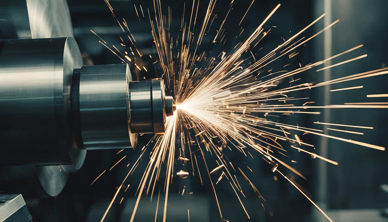
A lathe machine is a fundamental subtractive manufacturing tool engineered to produce cylindrical components with high precision. It operates by rotating a workpiece against a stationary, single-point cutting tool, systematically removing material to achieve the desired geometry. This process is central to creating parts requiring rotational symmetry across numerous industries.
This versatile machine tool has been a cornerstone of industrial production for centuries, evolving from manual operation to sophisticated computer numerical control (CNC) systems. Its core principle remains consistent: controlled material removal from a rotating workpiece.
Lathes are indispensable for shaping metals, plastics, and wood into various forms, including shafts, bushings, and intricate decorative pieces. The controlled interaction between the workpiece and the cutting tool ensures repeatable accuracy and surface quality.
The Lathe As a Cylindrical Shaping Machine Tool
The primary function of a lathe is to generate cylindrical or conical shapes by rotating a workpiece about its axis. This rotational motion, combined with linear tool movement, allows for the creation of complex external and internal features. The machine’s robust construction ensures stability during cutting operations.
Unlike milling machines that rotate the cutting tool, a lathe holds the workpiece in a chuck or collet and spins it at high speeds. The cutting tool then engages the rotating material, shearing away chips to form the desired profile. This method is exceptionally efficient for producing parts with rotational symmetry.
Modern CNC lathes integrate advanced controls, enabling automated and highly precise machining of intricate geometries. These machines are critical for mass production and for manufacturing components with tight tolerances, such as those found in aerospace and medical devices.
Rotational Workpiece Movement and Its Implications
| Parameter | Standard CNC Turning | Precision CNC Turning |
|---|---|---|
| Linear Tolerance | ±0.05 mm to ±0.13 mm (±0.002″ to ±0.005″) | ±0.01 mm to ±0.025 mm (±0.0004″ to ±0.001″) |
| Angular Tolerance | ±0.5° | ±0.25° |
| Surface Finish (Ra) | 0.8–1.6 µm (32–63 µin) | 0.4–0.8 µm (16–32 µin) |
Workpiece rotation is facilitated by the lathe’s spindle, housed within the headstock. The spindle’s rotational speed, measured in revolutions per minute (RPM), is a critical parameter that directly influences cutting performance and surface finish. Proper RPM selection is essential to achieve optimal surface feet per minute (SFM) at the cutting edge.
Workholding devices like three-jaw chucks, four-jaw chucks, and collets securely grip the workpiece, ensuring concentricity and preventing slippage during machining. Faceplates are used for irregularly shaped parts that cannot be held by conventional chucks.
The choice of workholding significantly impacts the rigidity of the setup, which in turn affects achievable tolerances and surface quality. Advanced chucks with integrated sensors are becoming more common, providing real-time data on clamping force for enhanced process reliability in automated environments.
Single-Point Cutting Mechanics in Lathe Operations
Lathe operations primarily utilize single-point cutting tools, characterized by a single cutting edge that engages the workpiece. The geometry of this cutting edge, including rake angles, clearance angles, and nose radius, is crucial for efficient chip formation, heat dissipation, and surface finish.
Rake angles, either positive or negative, dictate how easily the tool shears material and influences chip flow. Positive rake angles reduce cutting forces and are suitable for softer, ductile materials, while negative rake angles strengthen the cutting edge for harder, brittle materials.
Clearance (relief) angles prevent the tool’s flank from rubbing against the machined surface, minimizing friction and heat generation. A sufficient clearance angle, typically between 5° and 15°, is essential to avoid premature tool wear and poor surface finish.
Modern cutting tools often feature advanced materials like cemented carbides, ceramics, cubic boron nitride (CBN), and polycrystalline diamond (PCD), often enhanced with multi-layer coatings such as TiAlN or AlCrN. These innovations significantly extend tool life and enable higher cutting speeds, even with challenging materials.
Headstock and Tailstock: Core Structural Components
The headstock, located on the left side of the lathe, houses the main spindle, its bearings, and the gear train or motor that drives the workpiece rotation. It is the power transmission unit of the machine, providing the necessary torque and speed for cutting.
Opposite the headstock, the tailstock provides support for longer workpieces, preventing deflection and chatter during machining. It can also hold tools such as drills, reamers, or taps for operations performed along the workpiece’s rotational axis.
Connecting these two critical components is the lathe bed, a robust cast iron structure that provides the foundation and guides the carriage assembly. The carriage, comprising the saddle, cross-slide, and compound rest, moves along the bed, allowing precise positioning and feeding of the cutting tool.
Essential Lathe Operations: Turning, Facing, and Boring
Turning is the most common lathe operation, involving the removal of material from the external diameter of a rotating workpiece to create a cylindrical shape. This can include straight turning, taper turning, and contour turning to produce various profiles.
Facing involves cutting across the end of the workpiece to create a flat, perpendicular surface and to bring the part to its desired length. The cutting tool moves radially across the rotating face, ensuring a smooth and even finish.
Boring is an internal machining operation that enlarges an existing hole or creates an internal cylindrical feature. A boring bar, equipped with a single-point cutting tool, is fed into the workpiece to remove material from the inner diameter.
Other common lathe operations include grooving, which creates channels on the workpiece surface; threading, for cutting external or internal screw threads; and knurling, which produces a textured pattern for grip. Each operation requires specific tool geometry and machining parameters.
Modern Lathe Technology and Precision Standards
Modern CNC lathes offer unparalleled precision, often achieving standard tolerances of ±0.05 mm to ±0.13 mm for most turning operations. For critical applications, precision-grade machining can reach tolerances as tight as ±0.01 mm to ±0.025 mm under controlled conditions.
Surface finish, typically measured in Ra (arithmetic average roughness), is also a key indicator of quality. Standard CNC turning can achieve Ra 32–63 µin (0.8–1.6 µm), while fine turning can produce finishes as smooth as Ra 16–32 µin (0.4–0.8 µm).
Feeds and speeds are critical for optimizing material removal rates, tool life, and surface finish. For 304 stainless steel, coated carbide tools might use cutting speeds of 150–220 m/min, with roughing feed rates of 0.20–0.40 mm/rev.
Machining 6061 aluminum with carbide tools typically involves cutting speeds between 200–600 m/min (650-2000 SFM) for turning, with chip loads around 0.05–0.15 mm/tooth for milling. Proper chip evacuation and coolant application are essential to prevent built-up edge and ensure optimal results.
The table below outlines typical achievable tolerances and surface finishes for CNC turning operations: