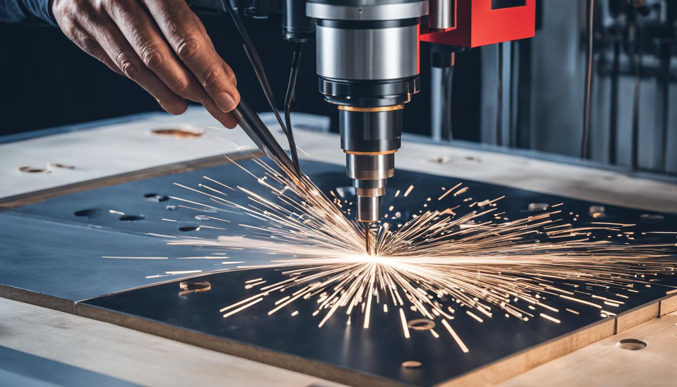
CNC machines, or Computer Numerical Control machines, are automated manufacturing systems that execute precise operations based on pre-programmed instructions. These versatile tools perform a wide range of functions, including cutting, drilling, milling, turning, and shaping various materials such as metal, plastic, wood, and composites. CNC machines operate by translating digital designs into a series of coordinated movements, controlling the position and speed of cutting tools or the material itself.
This process allows for highly accurate and repeatable production of complex parts and components. Modern CNC machines often incorporate multiple axes of movement, enabling them to create intricate 3D shapes and perform multiple operations in a single setup. They can also be equipped with tool changers, allowing for seamless transitions between different cutting tools and operations.
CNC technology has revolutionized manufacturing by increasing efficiency, reducing human error, and enabling the production of parts with tolerances that would be difficult or impossible to achieve manually. These machines are widely used in industries such as aerospace, automotive, electronics, and medical device manufacturing, where precision and consistency are paramount.
What is Computer Numerical Control (CNC)?
Computer numerical control (CNC) is a manufacturing method that utilizes preprogrammed computer software to automate the control, movement, and precision of machine tools. This innovative technology revolutionizes the manufacturing process by incorporating automated control into various cutting tools such as mills, lathes, routers, drills, grinders, water jets, and lasers. Furthermore, CNC can extend its control over non-machine tools like welding and electronic assembly machines too.
The CNC manufacturing method relies on creating a custom computer program written in a language called G-code. This program serves as a set of instructions and parameters that dictate the movements and functions of the machine tool.
How Does Computer Numerical Control Work?
In the CNC process, a computer program is created using a CAD drawing of the part to be manufactured. This program is usually written in G-code, an international standard language for CNC operations. The program is loaded onto the machine control unit (MCU), which is a microcomputer attached to the CNC machine. The MCU executes the program, controlling the machine’s movements and functions. The program contains instructions for feed rates, tool positioning, and other parameters.
Before running the program with the raw material in place, a test run is performed to ensure proper positioning and performance. This test run is essential to avoid damage to the machine and the part. When everything is ready, the CNC machine runs the program and completes the jobs with precision, whether it’s creating something from scratch, cutting a workpiece, or printing.

Example of G-code Program:
| G-code | Description |
|---|---|
| G01 | Linear interpolation (feed rate) |
| G02 | Clockwise circular interpolation |
| G03 | Counterclockwise circular interpolation |
| G04 | Dwell (pause) |
| G28 | Return to home position |
Benefits of Computer Numerical Control
CNC machines offer several benefits to manufacturers in various industries. These benefits include:
1. Cost Reduction:
CNC machines contribute to cost reduction by enabling precision manufacturing, increased production efficiency, scalability, and less material waste. The accuracy and repeatability of CNC machining eliminate the need for manual corrections and reduce errors, resulting in higher productivity and reduced material expenses.
2. Worker Safety:
CNC machines improve worker safety by minimizing the risk of accidents associated with manual handling of machinery. These machines can be operated remotely, reducing the need for operators to be physically present near the equipment. Additionally, remote handling allows for software upgrades and maintenance without direct human intervention, further enhancing worker safety.
3. Improved Precision:
One of the significant advantages of CNC machines is their ability to eliminate human error from the manufacturing process, leading to greater precision, complexity, speed, flexibility, and repeatability. This level of precision results in fewer defects in the final products, ensuring high-quality output consistently.
4. Waste Reduction:
CNC machines significantly reduce material waste due to their precise manufacturing capabilities. With CNC machining, manufacturers can optimize material usage and minimize scrap, leading to cost savings and a more sustainable production process.
5. Contour Machining:
CNC machines offer contour machining capabilities, allowing for the precise milling and production of contoured shapes. This feature is particularly useful in industries such as 3D printing and design, where complex and customized shapes are essential.
6. Integration with Enterprise Resource Planning:
Integrating CNC machines with enterprise resource planning (ERP) software and related applications can improve operational intelligence and reduce bottlenecks in production and manufacturing. Real-time data collection and analysis enable better decision-making and optimization of manufacturing processes.
| Benefits | Description |
|---|---|
| Cost Reduction | Precision manufacturing, increased production efficiency, scalability, and less material waste contribute to cost reduction. |
| Worker Safety | CNC machines minimize the risk of accidents by allowing remote handling and reducing the need for operators to be physically present near the equipment. |
| Improved Precision | Elimination of human error results in greater precision, complexity, speed, flexibility, and repeatability. |
| Waste Reduction | CNC machines optimize material usage, minimizing scrap and reducing waste. |
| Contour Machining | CNC machines enable the precise milling and production of contoured shapes, including those used in 3D printing and designs. |
| Integration with ERP | Integration with ERP software improves operational intelligence and reduces bottlenecks in production and manufacturing. |
Industries that Utilize Computer Numerical Control
CNC machines play a crucial role in various industries, including aerospace, medical, automotive, electronics, and oil and gas. These industries leverage the capabilities of CNC machines to enhance manufacturing processes and achieve precision results.
Aerospace Industry
In the aerospace industry, CNC machining is widely used to manufacture precise components for airplanes. These components include landing gear, airfoils, titanium shrouds, and more. CNC machines ensure the accuracy and quality required for the intricate parts used in the aerospace sector, contributing to the safety and performance of aircraft.
Medical Industry
The medical industry relies heavily on CNC machines to produce accurate and high-quality products. CNC machining is utilized in the manufacturing of implants, orthotic devices, and medical instruments. The precision and consistency offered by CNC machines are crucial in the medical field, where accuracy can significantly impact patient outcomes.
Automotive Industry
The automotive industry benefits greatly from CNC machining. CNC machines are instrumental in prototyping, producing large quantities of parts, and manufacturing various automotive components. From gearboxes and engine parts to dashboard panels, CNC machining ensures the precise manufacturing of automotive components.
Electronics Industry
CNC machining is vital in the electronics industry due to its accuracy, adaptability, and versatility. CNC machines are used in the production of consumer electronics, semiconductors, and printed circuit boards. These machines aid in achieving the intricate designs and precise specifications required for electronic components.
Oil and Gas Industry
The oil and gas industry relies on CNC machining to achieve the precise fit of parts used in large machinery. CNC machining plays a critical role in manufacturing drill bits, pistons, hydraulic components, and other crucial parts used in the exploration and extraction of oil and gas resources.
Overall, CNC machines have become indispensable in various industries, enabling manufacturers to achieve high precision, efficiency, and quality in their production processes.

History of Computer Numerical Control
The history of computer numerical control (CNC) machines can be traced back to the pioneering work of John Parsons in 1949. Parsons is credited with inventing the first numerical control machine, which utilized punch cards to control its movements. This early development laid the foundation for the revolutionary technology that would shape the future of manufacturing.
Over the years, CNC technology has undergone significant advancements. From the punch tape-controlled devices of the early days, CNC machines have evolved into sophisticated systems that accept CNC programming input and produce 3D machine parts with unparalleled precision.
In 1952, Richard Kegg made a significant contribution to the field of numerical control machining by improving the process, leading to the development of CNC milling machines. These machines allowed for more versatile and precise machining capabilities, expanding the possibilities for industries utilizing CNC technology.
The integration of digital computing in the 1960s marked a milestone in CNC technology. Punched tapes were replaced by computerized controls, enabling CNC machines to execute complex movements and functions with enhanced accuracy and efficiency.
Today, CNC machines continue to play a vital role in modern manufacturing processes. With advancements in computer technology, CNC machines have become even more versatile, enabling the production of intricate components for various industries.
| Year | Development |
|---|---|
| 1949 | John Parsons invents the first numerical control machine. |
| 1952 | Richard Kegg improves numerical control machining, leading to the development of CNC milling machines. |
| 1960s | Integration of digital computing replaces punched tapes with computerized controls. |
How CNC Machining Works
The CNC machining process involves several stages, each contributing to the successful execution of precise manufacturing operations. These stages include creating the CAD model, converting it to a CNC file, configuring the CNC machine, and executing the machining operation.
Create the CAD Model
The initial step in CNC machining is creating a CAD (Computer-Aided Design) model of the desired part. CAD software is used to design a 2D or 3D model, which serves as a digital representation of the final product.
Convert CAD Model to CNC File
Once the CAD model is complete, it needs to be converted into a CNC file. This file contains the instructions necessary for the CNC machine to accurately replicate the part. Typically, the CNC file is written in G code format, which specifies the machine’s movements, feed rates, and tool paths.
Configure the CNC Machine
Before beginning the machining operation, the CNC machine must be properly configured. This involves positioning the workpiece securely in the machine and adjusting the machine’s parameters to optimize performance. The configuration process ensures that the machine is ready to execute the desired operations with precision and efficiency.
Execute the Machining Operation
Once the CNC machine is configured and the CNC program is loaded, the machining operation can commence. The machine follows the instructions in the CNC file, carrying out the specified cutting, milling, drilling, or other machining operations. The machine continues executing the program until it reaches the end or is manually stopped.
Throughout the CNC machining process, careful attention to detail and accuracy is crucial. Each stage contributes to the overall success of the operation, ensuring that the final product meets the desired specifications with precision and efficiency.
Terminologies in CNC Machining
When working with CNC machining, it is important to understand key terminologies that are commonly used in the industry. Familiarizing yourself with these terms will enhance your knowledge and comprehension of the CNC machining process.
CAD
CAD, which stands for Computer-Aided Design, refers to software that is used to create graphical representations and models of the desired parts to be manufactured. CAD software enables engineers and designers to develop detailed designs and blueprints, incorporating precise measurements and specifications.
CAM
CAM, or Computer-Aided Manufacturing, is software that generates the necessary CNC programs from the CAD models. This software interprets the design information and generates the appropriate toolpaths and instructions that the CNC machine can understand and execute. CAM software plays a crucial role in translating the design into machine-readable instructions.
G-code
G-code is an alphanumeric language that provides instructions to the CNC machine on how to execute specific actions and movements. It controls the machine’s movements, feed rates, tool changes, and other functions. G-code is essential in CNC operations as it ensures precise and accurate machining.
M-code
M-code refers to miscellaneous machine codes in CNC machining that control non-cutting actions of the CNC machine. These codes include actions such as starting or stopping programs, activating coolant systems, initiating spindle rotations, and more. M-code commands assist in executing various machine functions and operations.
DNC
DNC stands for Distributed Numerical Control and is a system that enables multiple machine tools to be connected to a central server for synchronized working. This allows for efficient program management, making it easier to control and monitor CNC machines from a centralized location.
MDC
MDC, or Manufacturing Data Collection, refers to software that collects real-time data from CNC machines and operators. This data is then analyzed to gain insights and make improvements in production processes. MDC software provides valuable information on machine utilization, performance, and optimization opportunities.
| Terminology | Definition |
|---|---|
| CAD | Computer-Aided Design software used to create graphic representations of parts |
| CAM | Computer-Aided Manufacturing software that generates CNC programs |
| G-code | Alphanumeric language that instructs the CNC machine on movements |
| M-code | Machine codes controlling non-cutting actions of the CNC machine |
| DNC | Distributed Numerical Control for connected machine tools |
| MDC | Manufacturing Data Collection software for real-time data analysis |
Types of CNC Machining Processes
CNC machining encompasses various processes to shape and fabricate parts. Let’s explore the different types of CNC machining processes:
CNC Milling
CNC milling is a commonly used process that involves rotating cutting tools to remove material from a workpiece. It is ideal for creating complex shapes and features with high precision. CNC milling machines can perform both horizontal and vertical operations, allowing for versatile manufacturing.
CNC Drilling
CNC drilling focuses on creating holes in the workpiece using drill bits. The CNC machine precisely controls the drill’s movement and speed to ensure accurate hole placement. This process is widely utilized in industries such as aerospace, automotive, and electronics.
CNC Grinding
CNC grinding uses a rotating abrasive wheel to smoothen rough surfaces and achieve tight tolerances. It is primarily employed for precision grinding applications, ensuring the desired surface finish and dimensional accuracy of the workpiece. CNC grinding is commonly used in tool and die making, as well as in the production of precision components.
CNC Routing
CNC routing is similar to CNC milling, but with a slight difference. Instead of the workpiece moving, the cutting tool moves in X, Y, and Z dimensions while the workpiece remains stationary. This process is often used in woodworking, sign making, and the production of plastic or composite parts.
The choice of CNC machining process depends on the specific requirements and characteristics of the part being manufactured. Each process offers unique advantages and is selected based on factors such as material type, complexity of the design, required accuracy, and surface finish.
Conclusion
CNC machining is a highly versatile and precise manufacturing method that has revolutionized various industries, ranging from aerospace to medicine, automotive to electronics, and even oil and gas. By automating the control and movement of machine tools, CNC machines enable complex operations, exceptional precision, and improved efficiency. Understanding the fundamentals of CNC machining, its wide-ranging applications, and the different processes involved is crucial for manufacturers and engineers seeking to maximize the potential of this technology.
With CNC machining, manufacturers can achieve cost reduction, waste reduction, and improved worker safety. The precision and repeatability offered by CNC machines minimize defects and errors, resulting in high-quality final products. By utilizing contour machining capabilities, complex shapes and designs can be accurately reproduced, making CNC machining a valuable tool in various industries.
As CNC technology continues to advance, it is essential for manufacturers and engineers to stay updated on the latest developments and embrace the potential of CNC machining. By harnessing the power of CNC machines, businesses can elevate their manufacturing capabilities, streamline production processes, and stay competitive in today’s fast-paced market.