
Milling machines are foundational tools in modern manufacturing, precisely shaping materials like metal, plastic, and wood through the rotational motion of multi-edged cutting tools. This subtractive manufacturing process removes unwanted material to achieve desired geometries, ranging from flat surfaces and slots to complex profiles. Understanding the core principles and components of these machines is essential for any tooling engineer.
The fundamental principle involves a rotating cutter engaging a stationary or moving workpiece, systematically removing chips. This controlled mechanical force, primarily through shearing, crushing, impact, and abrasion, transforms raw material into finished parts with specific dimensions and surface finishes.
Mechanical Milling Fundamentals
Milling is a machining process characterized by geometrically defined cutting edges, distinguishing it from abrasive processes like grinding. The milling cutter, typically featuring multiple cutting edges, rotates at high speed while the workpiece is securely clamped to a machine table.
As the rotating cutter contacts the workpiece, it removes material, forming chips. This action can create flat surfaces, grooves, slots, and intricate contours with high accuracy. The interaction between the tool’s geometry and the material’s properties dictates chip formation and overall machining efficiency.
Two primary methods define milling operations: conventional (up) milling and climb (down) milling. In conventional milling, the cutter rotates against the workpiece’s feed direction, generating more friction and heat. Conversely, climb milling involves the cutter rotating in the same direction as the feed, which generally results in less friction, reduced heat, and improved surface finish.
Tool geometry significantly influences the machining process, affecting chip formation, cutting forces, and surface quality. Key angles such as rake, clearance, and helix angles are optimized based on the workpiece material and desired outcome. For instance, a higher helix angle can increase tool sharpness and improve chip evacuation, especially in ductile materials.
Essential Milling Machine Components
| Parameter | Description | Typical Range/Value |
|---|---|---|
| Spindle Speed (RPM) | Rotational speed of the cutting tool | Varies widely by material, tool, and diameter |
| Feed Rate (IPM/mm/min) | Rate of tool or workpiece advancement | Varies widely by material, tool, and chip load |
| Standard CNC Milling Tolerance | Achievable dimensional accuracy | ±0.005″ (±0.13 mm) for general work |
| High-Precision CNC Milling Tolerance | Achievable dimensional accuracy for critical parts | ±0.0005″ (±0.013 mm) or tighter |
| ISO 2768-m (Medium) | General linear tolerance for machined parts | ±0.1mm to ±0.2mm (depending on size) |
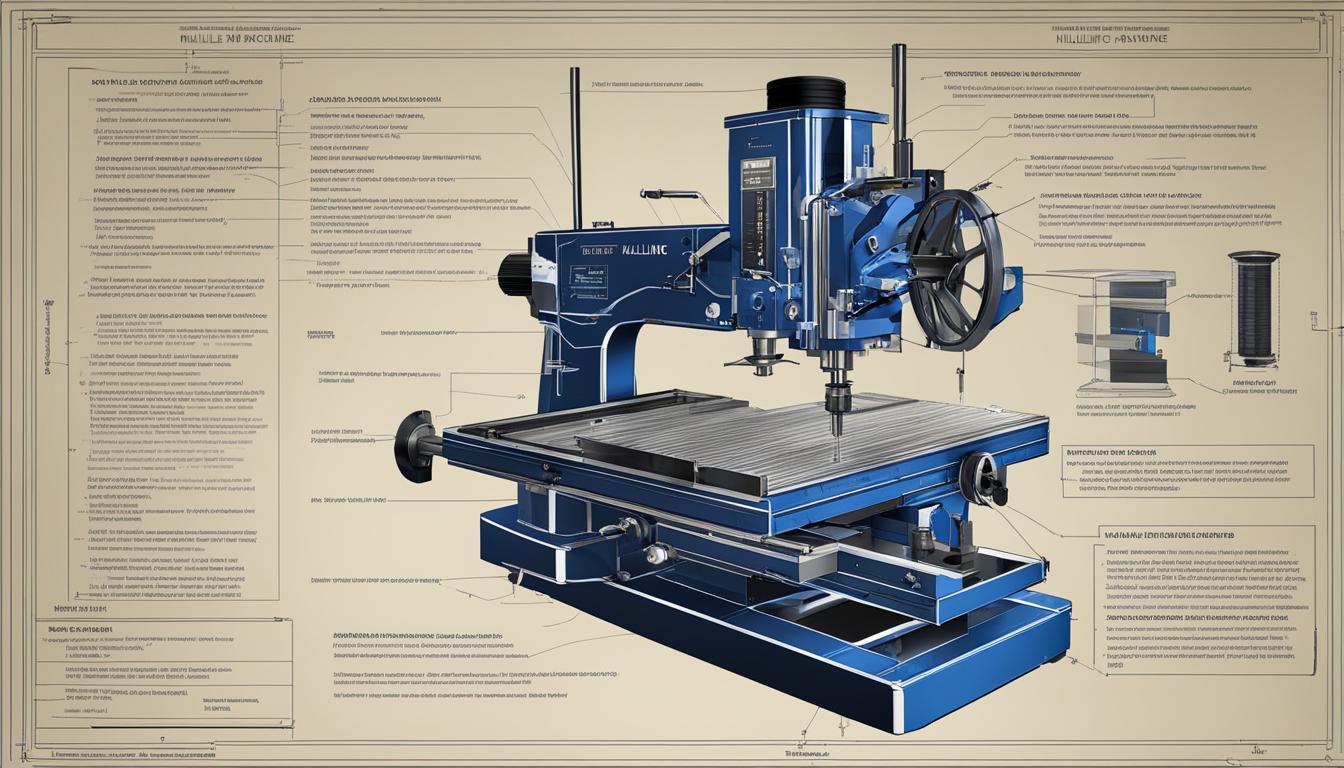
A milling machine’s robust construction ensures stability and precision during material removal. The base, typically made of cast iron, provides a rigid foundation, dampening vibrations and often housing the coolant reservoir. Rising vertically from the base, the column supports the spindle and motor assembly.
The knee, a substantial casting, mounts on the column’s front face and moves vertically to adjust the distance between the cutter and the workpiece. Resting on the knee, the saddle moves transversely (Y-axis), while the table, positioned atop the saddle, provides longitudinal (X-axis) movement. T-slots on the table facilitate secure clamping of workpieces and fixtures.
The spindle is a critical rotating shaft that holds and drives the cutting tool. It features an internal taper for tool mounting and is powered by a motor, which determines the machine’s cutting capacity. In vertical mills, the spindle head often allows for tilting and quill extension for fine vertical (Z-axis) adjustments.
Modern milling machines, particularly Computer Numerical Control (CNC) models, integrate advanced control systems. These systems precisely dictate the movement of the cutting tool across multiple axes, enabling complex geometries and high repeatability. Manual machines, however, rely on handwheels for axis movement.
Precision in Practice: Speeds, Feeds, and Tolerances
Optimizing cutting parameters is crucial for achieving desired surface finishes, extending tool life, and managing spindle load. Surface speed (Vc or SFM) refers to the speed at which the cutting edge passes through the material, directly impacting heat generation and tool wear. Feed rate (Vf or IPM) is the rate at which the workpiece or tool advances, influencing chip thickness and tool load.
Calculating spindle speed (N) in revolutions per minute (RPM) from surface speed (SFM) is a fundamental step. The formula is N = (SFM × 3.82) / D, where D is the cutter diameter in inches. For metric calculations, N = (Vc × 1000) / (π × D), with Vc in m/min and D in mm.
Feed rate (Vf) is then calculated using the formula Vf = N × fz × z, where fz is the feed per tooth (chip load) and z is the number of effective flutes on the cutter. These calculations ensure optimal chip formation and prevent premature tool wear.
Modern CNC milling machines can achieve impressive tolerances, often reaching ±0.005 mm or even higher in high-end systems. Factors like machine rigidity, ball screw quality, and spindle runout significantly influence this precision. For general work, a standard tolerance of ±0.005 inches (±0.13 mm) is commonly achievable.
Operational Safety and Best Practices
Operating a milling machine demands strict adherence to safety protocols to prevent injuries and equipment damage. Personal Protective Equipment (PPE) is mandatory, including safety glasses with side protectors, and appropriate footwear. Loose clothing, jewelry, and long hair must be secured to prevent entanglement with moving parts.
Before starting any operation, pre-operational checks are essential. These include ensuring the work area is free of slip/trip hazards, machine guards are in place, and the cutter is in good condition and securely mounted. Familiarity with the ON/OFF starter and emergency stop (E-Stop) is critical.
During operation, hands must be kept clear of moving machine parts and cutting tools. Never leave a running machine unattended. Workpieces require secure clamping with minimal overhang to prevent movement during cutting. Chips should be removed with a brush or suitable tool only after the machine has come to a complete standstill, never by hand or compressed air.
Modern Milling Technology and Resources
The evolution of milling technology has progressed significantly from manual machines to sophisticated CNC systems. Computer Numerical Control automates operations, offering unparalleled accuracy, repeatability, and the ability to produce complex geometries that were once impossible. This advancement has made milling indispensable across industries like aerospace, medical technology, and automotive.
Advanced tooling, including solid carbide end mills with specialized coatings like TiN, TiCN, and AlTiN, further enhances machining performance. These coatings increase hardness, lubricity, and thermal resistance, prolonging tool life and improving surface finish, especially when machining challenging materials.
Engineers and machinists rely on comprehensive technical resources, including textbooks and digital manuals, to master milling practices. These guides often detail machine components, operational procedures, and advanced techniques. Continuous learning through such resources is vital for staying current with modern engineering practices and optimizing machining processes.