
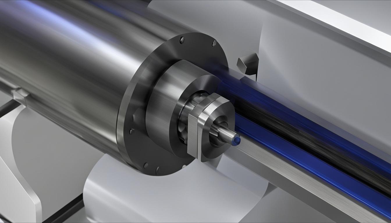
Turning is a fundamental machining process that precisely shapes a workpiece by removing material. This subtractive manufacturing method involves rotating the workpiece against a stationary, single-point cutting tool. The controlled interaction between the rotating material and the cutting tool produces cylindrical, conical, helical, or spherical forms.
The process is highly versatile, capable of producing both external and internal features on a part. Modern turning operations, especially those utilizing Computer Numerical Control (CNC) technology, achieve high precision and excellent surface finishes across various materials, including metals, plastics, and even wood.
Turning: the Machining Process Defined
Turning constitutes a specific machining operation where a workpiece rotates rapidly around its axis while a cutting tool removes excess material. This action decreases the diameter, forms threads, or carves intricate patterns, ultimately shaping the stock into the desired component.
Various turning operations exist, each designed for specific geometries. Common examples include facing, which squares the ends of a workpiece, and boring, which enlarges or creates internal holes. Threading, parting, and grooving are also essential turning operations, demonstrating the process’s broad capabilities.
The efficiency of turning operations is significantly influenced by parameters such as cutting speed, feed rate, and depth of cut. These variables directly impact material removal rates, surface finish, and tool life. Optimizing these parameters is crucial for achieving desired part quality and manufacturing efficiency.
Lathe: the Machine Tool Platform
| Nominal Length Range (mm) | Fine (f) | Medium (m) | Coarse (c) | Very Coarse (v) |
|---|---|---|---|---|
| 0.5 to 3 | ±0.05 | ±0.1 | ±0.2 | — |
| >3 to 6 | ±0.05 | ±0.1 | ±0.3 | — |
| >6 to 30 | ±0.1 | ±0.2 | ±0.5 | ±1 |
| >30 to 120 | ±0.15 | ±0.3 | ±0.8 | ±1.5 |
| >120 to 400 | ±0.2 | ±0.5 | ±1.2 | ±2.5 |
| >400 to 1000 | ±0.3 | ±0.8 | ±2 | ±4 |
| >1000 to 2000 | ±0.5 | ±1.2 | ±3 | ±6 |
| >2000 to 4000 | ±0.8 | ±2 | ±4 | ±8 |
A lathe is the machine tool specifically designed to perform turning operations. It functions by rotating a workpiece about a central axis, allowing a cutting tool to remove material from its surface. This rotational motion is the defining characteristic that differentiates a lathe from other machine tools like milling machines, where the tool rotates.
Lathes range from traditional manual engine lathes to sophisticated CNC turning centers. While manual lathes require continuous operator supervision, CNC lathes automate the process, enabling intricate designs and high precision through computer programming.
Modern turning centers, often equipped with multi-axis capabilities and ‘live tooling,’ extend beyond basic turning. These advanced machines can perform milling, drilling, and tapping operations within a single setup, significantly reducing part turnaround times and enhancing overall efficiency.
Mechanics of Single-Point Turning
Single-point cutting tools, characterized by having only one primary cutting edge, are fundamental to turning, boring, and shaping operations. The tool’s geometry, including rake angle, relief angle, and nose radius, critically influences chip formation and surface finish.
During machining, the material ahead of the cutting tool undergoes plastic deformation and shearing, forming a chip that flows along the tool’s rake face. This chip formation process is complex, involving primary and secondary deformation zones where significant friction and heat are generated.
Chip types vary depending on the workpiece material and cutting conditions. Ductile materials often produce continuous chips, while brittle materials or unfavorable cutting conditions can result in discontinuous or segmented chips. Effective chip control, often through chip breakers, is vital for preventing entanglement, reducing vibration, and improving tool life.
Lathe Hardware and Workholding
The fundamental components of a lathe include the bed, headstock, tailstock, spindle, chuck, carriage, cross-slide, and tool post. The bed provides the machine’s base and alignment, while the headstock houses the spindle and drive system that rotates the workpiece.
Workholding devices are crucial for securely gripping the workpiece, ensuring concentricity, rigidity, and safety during operation. Common methods include three-jaw self-centering chucks for round or hexagonal stock, and four-jaw independent chucks for irregular shapes or eccentric work. Collets are often used for smaller or longer workpieces, offering high precision.
Modern CNC lathes frequently incorporate advanced workholding solutions, such as low-pressure hydraulic fixtures or custom soft jaws. These are particularly important for delicate materials like engineering plastics or for achieving micron-level accuracy in demanding applications like aerospace and medical device manufacturing.
Achieving Cylindrical Part Geometry and Precision
Producing cylindrical components with precise dimensional control is the core purpose of turning. Lathes excel at creating shafts, bores, threads, and tapers to tight tolerances, which is critical across various industries.
Standard tolerances for turned parts are often governed by international standards like ISO 2768-1 for linear and angular dimensions. This standard provides four tolerance classes: fine (f), medium (m), coarse (c), and very coarse (v), allowing manufacturers to specify appropriate precision levels.
Achieving high precision in turning requires careful consideration of cutting tool materials, coatings, and optimized geometries. Advanced materials like cemented carbides with specialized coatings (e.g., TiN, TiCN, DLC) enhance wear resistance, reduce friction, and improve surface quality, enabling faster machining speeds and extended tool life.
For critical applications in aerospace and medical industries, precision turning often demands tolerances within ±0.005 mm. This level of accuracy necessitates state-of-the-art CNC turning centers, multi-axis capabilities, and rigorous quality control, including in-process monitoring and sophisticated metrological techniques.
The table below outlines typical general tolerances for linear dimensions according to ISO 2768-1, which are applied when specific tolerances are not explicitly indicated on engineering drawings.