
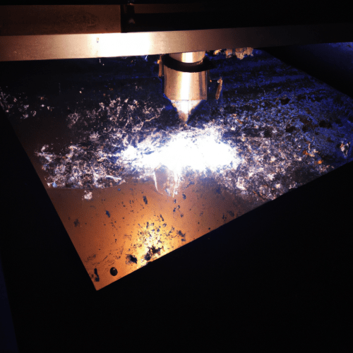
Plasma cutting aluminum is a highly effective and widely adopted process in modern fabrication, shipbuilding, and automotive sectors. While aluminum’s unique thermal properties necessitate specific parameter adjustments compared to steel, contemporary plasma systems deliver excellent cut quality and high productivity. Understanding these distinctions is key to achieving optimal results.
Aluminum’s high thermal conductivity means it dissipates heat rapidly from the cut zone, requiring faster travel speeds to maintain a stable arc and prevent excessive heat input into the workpiece. Its lower melting point, around 660°C, also influences cutting dynamics, making precise control of amperage and speed crucial for clean edges.
Optimizing High-Amperage Plasma Settings for Aluminum
Achieving superior cut quality on aluminum with plasma systems hinges on precise amperage and travel speed synchronization. Fabricators should always consult the machine manufacturer’s cut charts as a foundational starting point for specific material thicknesses and consumable sets. Deviating significantly from these recommendations can accelerate consumable wear and compromise cut integrity.
Running the highest amperage permissible for a given aluminum thickness generally yields faster cuts, a narrower heat-affected zone (HAZ), and reduced distortion. However, this must be balanced with travel speed; cutting too slowly with high amperage can lead to excessive heat accumulation, a wider kerf, and heavy bottom dross. Conversely, insufficient amperage or excessive speed results in incomplete penetration and beveling.
For automated systems, torch standoff height is critical, typically set around 1.5mm (0.060 inches) above the workpiece. Pierce height should be 1.5 to 2 times the cutting height to prevent molten aluminum blowback from damaging the nozzle and other consumables. Modern CNC systems with auto arc voltage height control maintain consistent standoff, even on warped plates.
Strategic Gas Selection: Nitrogen and Argon-Hydrogen Blends
| Aluminum Thickness | Plasma Gas | Shield Gas | Typical Amperage Range |
|---|---|---|---|
| < 5 mm (0.188″) | Nitrogen (N₂) | Nitrogen (N₂) or Air | 45 A – 65 A |
| 6 mm – 12 mm (0.25″ – 0.5″) | Nitrogen (N₂) | Water (H₂O) | 65 A – 130 A |
| > 20 mm (0.75″) | Argon-Hydrogen (H-35) | Nitrogen (N₂) | 130 A – 260 A |
Gas selection profoundly impacts cut speed, edge appearance, dross formation, and overall operating cost when plasma cutting aluminum. Compressed air offers an economical and accessible option for general-purpose cutting, particularly on thinner aluminum, though it may result in more oxidation on the cut edge.
For enhanced cut quality and reduced oxidation on aluminum less than 5 mm (0.188 inches) thick, nitrogen (N₂) is recommended as both the plasma and shield gas (N₂/N₂ process). This combination provides a good balance of quality and affordability. For slightly improved results, CO₂ can be used as a secondary gas with nitrogen plasma.
Cutting aluminum thicker than 6 mm (0.250 inches) often benefits from a nitrogen plasma with a water shield, which produces a smooth surface finish and excellent cut speeds. For very thick aluminum, exceeding 20 mm (0.75 inches), a mixture of 35% hydrogen and 65% argon (H-35) as the plasma gas, with nitrogen as the shield gas, delivers maximum cutting capability and a very smooth, almost polished surface.
Minimizing Dross Formation and Managing Cut Quality
Dross, the resolidified molten metal clinging to the cut edge, is a common challenge in plasma cutting aluminum. While some dross is often unavoidable, especially on thicker material, effective management significantly reduces post-cut cleanup. Dross formation is primarily influenced by cutting speed, amperage, torch height, and consumable condition.
Optimizing travel speed is paramount; cutting too fast causes hard, high-speed dross on the bottom edge, while cutting too slowly results in softer, low-speed dross on the top and a wider kerf. Maintaining the correct torch height and ensuring a consistent, dry, and clean air supply are also critical for arc stability and minimizing dross. Worn consumables, such as electrodes and nozzles, can also lead to excessive dross and should be replaced at the first signs of wear.
Modern engineering practices emphasize using manufacturer-validated cut charts and implementing lead-ins and lead-outs to initiate and terminate cuts away from the finished part. This practice helps to localize the ‘messiest’ part of the cut, which is typically the pierce event, to the scrap material. Consistent grounding and stable fixturing further contribute to repeatable, high-quality cuts.
Controlling the Heat-Affected Zone (HAZ)
The heat-affected zone (HAZ) is an area where the aluminum’s microstructure changes due to the heat input from the plasma arc, potentially impacting its mechanical properties. While completely eliminating HAZ in thermal cutting is impossible, its size can be significantly reduced through optimized parameters and techniques.
Managing heat input during cutting is crucial. Higher travel speeds, coupled with appropriate amperage settings, minimize the duration of heat exposure, thereby reducing the HAZ width. Water-cooled systems and allowing adequate cooling time between cuts, especially for intricate designs or thin sheets, also help to dissipate heat and prevent warping.
Emerging technologies, such as high-definition plasma systems and water-injection plasma cutting, offer advanced HAZ control. Water injection uses a water curtain to cool the cut, significantly reducing heat distortion and resulting in cleaner edges. These advancements are particularly beneficial for applications requiring stringent material integrity.
Navigating Plate Thickness Limits and Modern Tolerances
Plasma cutters demonstrate remarkable versatility in cutting aluminum, ranging from thin gauge sheet to substantial plate thicknesses. Modern industrial plasma systems can cleanly sever aluminum from 1 mm (0.04 inches) up to 152 mm (6 inches) thick, depending on the machine’s amperage class and the gas combination employed.
For thinner aluminum, below 1 mm, plasma’s wider kerf and significant heat input can induce more warping than cutting. Production shops typically utilize 65 A or 85 A systems for routine plate work over 12 mm (0.5 inches), while higher-amperage machines (e.g., 260 A) are reserved for very thick sections.
Standard tolerances for general-purpose CNC plasma cutting systems typically range from ±0.5 mm to ±1 mm. High-definition plasma systems, however, can achieve significantly tighter tolerances, often as precise as ±0.25 mm, making them suitable for aerospace, automotive, and other applications demanding intricate designs and exact fits.