
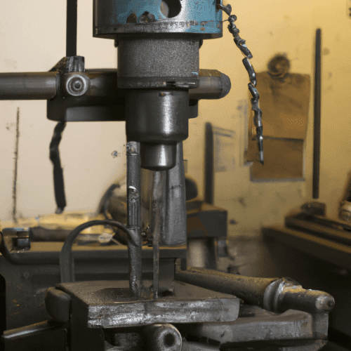
Acquiring a drill press represents a significant investment for any workshop, demanding careful consideration of technical specifications and operational capabilities. This guide provides an in-depth analysis of critical factors, ensuring a well-informed decision for both hobbyists and professional machinists.
Drill presses offer superior accuracy and repeatability compared to handheld drills, making them indispensable for creating precise, perpendicular holes. Understanding the distinctions between various models and their features is paramount for optimizing drilling operations across diverse materials.
Benchtop versus Floor Drill Press Selection
Benchtop drill presses are compact units designed for mounting on a workbench, offering a smaller footprint and portability. They are well-suited for small-scale projects involving wood, plastics, and lighter metals, providing essential features like adjustable speed, depth stops, and tilting tables.
Floor-standing drill presses, conversely, are larger, heavier machines intended for permanent floor mounting. These models typically boast greater power, increased torque, and a more substantial column, making them ideal for drilling larger holes in tougher materials such as dense hardwoods and various steels.
The primary mechanical difference between benchtop and floor models often lies in column length and base size, though floor models frequently offer larger chucks and greater throat clearance for bigger workpieces. Radial drill presses, a specialized variant, feature a horizontal column allowing the spindle to move radially, facilitating drilling in the center of very large workpieces without repositioning.
Motor Horsepower and Spindle Speed Control
| Feature | Benchtop Drill Press | Floor Drill Press |
|---|---|---|
| Motor Horsepower (Typical) | 1/4 HP to 3/4 HP | 3/4 HP to 1.5 HP+ |
| Spindle Speed Range (RPM) | ~500 – 3600 RPM | ~60 – 3600 RPM (wider range) |
| Quill Stroke Depth | 2″ to 3.25″ | 4″ to 6″+ |
| Spindle Taper | MT1, MT2 | MT2, MT3, MT4 |
| Drilling Capacity (Steel) | Up to 1/2″ – 5/8″ | Up to 1-1/4″+ |
| Typical Hole Tolerance | ±0.05 mm to ±0.1 mm | ±0.02 mm to ±0.05 mm (with reaming/boring) |
Motor horsepower (HP) directly correlates with a drill press’s ability to handle demanding drilling tasks and larger drill bits. For lighter metals like aluminum or smaller holes, a 1/4 to 1/3 HP motor may suffice. However, drilling through stainless steel or iron, especially with larger bits, necessitates at least 1 HP.
Spindle speed, measured in revolutions per minute (RPM), is crucial for effective drilling across different materials and drill bit types. A broad RPM range, from as low as 60 RPM to as high as 3600 RPM, allows for optimal cutting performance, preventing bit squealing or overheating.
Modern drill presses often feature variable speed settings, either through belt changes on stepped pulleys or electronic controls, enabling precise RPM adjustments. This flexibility is vital for matching the correct cutting speed to the material and drill diameter, which directly impacts hole quality and tool life.
Quill Stroke Depth and Drilling Capacity
Quill stroke, also known as spindle travel, defines the maximum depth a drill bit can penetrate in a single, continuous feed. This specification is critical for through-hole drilling in thick materials and for applications requiring consistent depth control.
Home workshop models typically offer a quill stroke between 2 to 3-1/4 inches. Industrial or larger floor models can provide significantly greater travel, often exceeding 4 inches, which is essential for deeper holes and larger workpieces.
An adjustable depth stop is a standard feature on most drill presses, ensuring repeatable drilling to a precise depth without guesswork. For exceptionally deep holes, exceeding three times the drill diameter, techniques like peck drilling or repositioning the workpiece may be necessary to clear chips and prevent heat buildup.
Spindle Taper Sizes and Tooling Compatibility
The spindle taper is a standardized conical interface within the drill press spindle, designed to securely hold drill chuck arbors, taper shank drills, and other tooling. The most prevalent standard in machining is the Morse Taper (MT), developed in the 1860s.
Morse Tapers range in size from MT0 to MT7, with MT1, MT2, MT3, and MT4 being the most common in workshop settings. Benchtop machines frequently utilize MT1 or MT2, while quality floor-standing models often feature MT3 or MT4 for heavier duty drilling.
This self-holding taper relies on friction for tool retention, providing accurate centering and quick tool changes without drawbars or clamping screws. Proper identification of your machine’s MT size, typically found in the manual or by measuring the large diameter of the female taper, is crucial for selecting compatible tooling.
Table Tilt Mechanisms and Workholding
Drill press tables are designed to provide a stable platform for workpieces, with many models featuring mechanisms for tilting. A tilting table allows for drilling at angles other than 90 degrees relative to the spindle, expanding the machine’s versatility for specialized applications.
Precision in table tilt mechanisms is paramount; however, re-squaring the table after angled operations can be challenging for some users. Accessories like angle drilling tables offer alternative solutions, providing precise control over workpiece angle without adjusting the main drill press table.
Workholding is equally critical for safety and accuracy. Utilizing vises, clamps, or specialized jigs to secure the workpiece to the table prevents rotation and ensures consistent hole placement. The table’s size and adjustability also influence the maximum workpiece dimensions that can be effectively processed.