
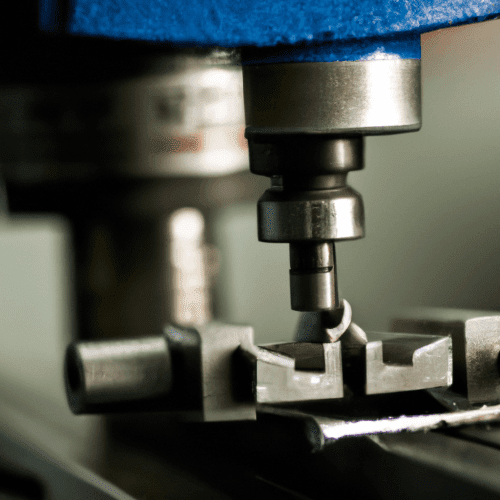
Finger mills, a specialized category of end mills, are indispensable tools in modern CNC machining for creating precise, intricate features. These cutters are distinguished by their smaller diameters and often longer aspect ratios, making them ideal for operations where standard end mills are too large or lack the necessary reach. Their application spans from deep slotting to fine profile work, demanding careful consideration of tool geometry, material, and machining parameters.
Understanding the capabilities and limitations of finger mills is crucial for achieving optimal surface finish, dimensional accuracy, and tool life. Proper selection and application directly impact the efficiency and quality of the machined component, particularly in industries requiring high precision like aerospace, medical, and mold making. This guide explores the technical depths of finger mill applications, offering insights into best practices and critical considerations.
Deep Slotting Operations
Deep slotting, defined as cutting slots with a depth exceeding approximately three times the tool diameter, presents significant challenges in CNC machining. Finger mills are frequently employed for these tasks, especially when creating closed slots, keyways, or internal channels. Success hinges on managing tool deflection, chip evacuation, and heat generation effectively.
Effective strategies for deep slotting include using ramped entries or trochoidal milling paths instead of plunging directly into the material. Ramped entries reduce shock loads on the tool, while trochoidal milling, which involves spiral-like passes with controlled radial engagement, helps equalize chip thickness and minimize stress on the cutting edge. This technique can reduce radial forces by about 40%, allowing tools to withstand higher cutting forces for longer durations.
Chip evacuation is paramount in deep slots, as trapped chips can lead to recutting, heat buildup, and tool breakage. Utilizing through-spindle coolant, high-pressure coolant, or a directed air blast is essential to clear the cutting zone. Programming retract paths with a slight hook or lift ensures the tool clears the wall before rapid travel, preventing chips from being re-cut.
Narrow Keyway Cutting
| Parameter | Aluminum (6061) | Steel (Mild) | Stainless Steel (304) |
|---|---|---|---|
| Recommended SFM (Surface Feet per Minute) | 800 – 1800 | 450 – 600 | 100 – 350 |
| Typical RPM (for small diameter tools) | 12,000 – 24,000+ | 6,000 – 8,000 | 2,700 – 8,000 (varies by diameter) |
| Feed Rate (mm/min or IPM) | 800 – 2500 mm/min (or 8-24 IPM for small tools) | 300 – 600 mm/min | Varies by chip load (e.g., 445 mm/min for 8mm 4-flute) |
| Standard Milling Tolerance | ±0.001 – ±0.002 inch (±0.025 – ±0.051 mm) | ±0.001 – ±0.002 inch (±0.025 – ±0.051 mm) | ±0.001 – ±0.002 inch (±0.025 – ±0.051 mm) |
| Precision Milling Tolerance | Up to ±0.0005 inch (±0.012 mm) | Up to ±0.0005 inch (±0.012 mm) | Up to ±0.0005 inch (±0.012 mm) |
| Recommended Carbide Grade | Submicron 7.5-10%Co (K10-K40, C-2/C-3) | Submicron 10%Co (K20-K40, C-2) or C-5 for steel | AlCrN or TiAlN coated carbide |
Cutting narrow keyways requires exceptional precision and rigidity, making finger mills a primary choice. Keyways are critical features for transmitting torque between shafts and components, demanding tight tolerances for both width and depth. Typical keyway width and depth tolerances often range from +/-0.001 inch to +/-0.002 inch, with precision fits sometimes requiring +/-0.0005 inch.
When milling keyways, the workpiece must be securely clamped to prevent rotation. The cutter needs to be precisely centered relative to the shaft. For square-end keyways, a plain or side milling cutter can be used, while rounded keyways require an end milling cutter of the appropriate diameter.
Proper feed rate, spindle speed, and cutting depth are crucial settings that directly influence the quality of the keyway. Machinists should start with shallow cuts and proceed gradually to achieve the desired width and length, consistently applying coolant to manage heat.
Small Profile Milling
Small profile milling involves machining intricate two-dimensional and three-dimensional contours on a workpiece, including slots, pockets, and complex curved surfaces. Finger mills, particularly those with smaller diameters, are ideal for these applications, enabling the creation of features with high dimensional accuracy and smooth surface finishes.
The process typically involves multiple stages: roughing, semi-finishing, and finishing. Roughing removes the bulk of the material, often using larger tools, while subsequent stages employ progressively smaller finger mills to refine the shape and achieve the desired surface quality and tight tolerances.
Maintaining consistent wall thickness and minimizing tool overhang are critical for stability during profiling operations. Long tool overhangs amplify runout and deflection, especially when exceeding three times the tool diameter, which can lead to dimensional inaccuracies and poor surface finish.
Precision Channel Milling
Precision channel milling, a subset of slot milling, focuses on creating highly accurate and often deep grooves or channels. These operations are fundamental in industries like aerospace and electronics for components requiring precise fluid routing, wire management, or intricate assembly features.
The selection of the right finger mill for channel milling depends on the material, desired channel dimensions, and required surface finish. For deep channels, using longer end mills with reinforced cores or side milling cutters supported by an arbor can help maintain consistent radial cutting forces and reduce tool deflection.
Modern CAM software and advanced toolpath strategies, such as trochoidal milling, can significantly boost productivity by 25–40% in channel milling, while also improving chip evacuation and reducing heat. This is particularly beneficial for narrow channels or materials that generate high cutting resistance.
End Mill Sizing and Selection
Selecting the appropriate finger mill involves considering several critical factors, including material, diameter, flute count, coating, and carbide grade. The tool’s diameter is directly related to its strength; miniature end mills (under 1/8 inch diameter) are considerably weaker and require tighter tolerances and careful handling.
Carbide grades are chosen based on the workpiece material and machining conditions. For instance, C-2(m) carbide is a general-purpose grade suitable for non-ferrous materials and some steels, offering good wear resistance. C-5 carbide, being harder and more brittle, is typically reserved for machining steel due to its greater wear resistance.
Coatings like Titanium Nitride (TiN), Titanium Carbonitride (TiCN), Titanium Aluminum Nitride (TiAlN), and Aluminum Chromium Nitride (AlCrN) enhance tool life and performance. TiAlN and AlCrN are particularly effective for machining challenging materials like stainless steel, titanium, and hardened steels due to their high temperature and wear resistance.
Feeds, Speeds, and Tolerances for Finger Mills
Optimizing feeds and speeds for finger mills is crucial for tool longevity and part quality. These parameters depend heavily on the material, tool diameter, number of flutes, and desired chip load. For aluminum, high speeds (up to 33,000 RPM for some tools) and feed rates are common, with recommended surface feet per minute (SFM) often between 800-1800.
When machining steel, slower speeds are generally advised to prevent excessive heat generation due to material toughness. Maintaining a proper chip load is key; feeding too slowly can cause friction and heat, while feeding too fast can overload the tool.
Runout, the deviation of a rotating tool from its true central axis, significantly impacts tool life and surface finish, especially with small diameter finger mills. For precision work, runout should ideally be kept under 0.0005 inch. Even a small amount of runout can cause uneven tool loading and premature wear.