A turning lathe is a versatile machine tool that is used to shape wooden or metallic products. With origins dating back to ancient Egypt in 1300 BCE, the lathe has evolved over the centuries into a vital component of modern manufacturing. Today, it serves various industries, including metalworking, thermal spraying, glass processing, and woodworking.
The lathe machine performs a wide range of fabricating operations, such as sanding, drilling, cutting, deformation, and most notably, turning. Turning is the process of removing material from a workpiece to create a desired shape and finish. It involves rotating the workpiece while a stationary cutting tool selectively removes material.
Lathe machines are often referred to as the “Mother of All Machine Tools” due to their versatility and ability to create complex shapes. From producing intricate metal components to crafting ornate wooden pieces, turning lathes play a vital role in the manufacturing world.
In the following sections, we will delve deeper into how lathe machines work, the different types of lathes, the products they can create, the turning process, and much more. Whether you’re a seasoned professional or a novice enthusiast, this article will provide valuable insights into the fascinating world of turning lathes.
How Does a Lathe Work?
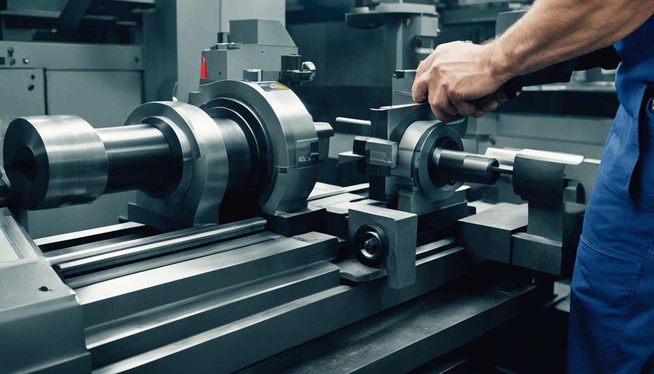
A lathe machine works by rotating the workpiece about an axis while a stationary cutting tool removes material to shape the piece. This process is known as lathe operation. The machine consists of several essential parts that contribute to its functionality.
Lathe Parts
Here are the key parts of a lathe:
| Part | Description |
|---|---|
| Headstock | The headstock contains the main spindle, which holds and rotates the workpiece. It is driven by a motor and is responsible for the primary movement of the lathe. |
| Tailstock | The tailstock provides support to the opposite end of the workpiece, stabilizing it during the lathe operation. It can be adjusted to accommodate different lengths of workpieces. |
| Spindle | The spindle is connected to the motor in the headstock and is responsible for rotating the workpiece at the desired speed. |
| Cutting Tools | A lathe uses various cutting tools to remove material from the workpiece. Different types of cutting tools are used depending on the desired shape and material. |
Additionally, the workpiece is placed between the headstock and tailstock and secured with a chuck. The tool holder holds the cutting tool at an appropriate distance from the workpiece. This arrangement allows for precise shaping and machining of the workpiece.
Overall, the combination of rotating the workpiece and manipulating the cutting tools enables a lathe machine to shape materials with accuracy and precision.
Types of Lathe Machines
There are several types of lathe machines available today, each designed for specific applications. The two most commonly used types are woodworking lathes and metal lathes. Let’s take a closer look at each type:
Woodworking Lathe
Woodworking lathes are specifically designed to shape and refine wooden objects. These lathes are essential tools for woodturners, craftsmen, and hobbyists who work with wood. Woodworking lathes allow for precision cutting, sanding, shaping, and detailing of wooden pieces. With the help of chisels, gouges, and other cutting tools, woodworkers can create intricate designs and achieve smooth finishes. Woodworking lathes come in various sizes, from benchtop models for small projects to larger floor-standing models for professional workshops.
Metal Lathe
Metal lathes are used to shape and manipulate metal objects. These lathes are widely used in industries such as automotive, aerospace, and manufacturing. Metal lathes provide precise control over cutting tools, allowing machinists to create complex shapes and threads on metal workpieces. They can handle various metals, including steel, aluminum, and brass. Metal lathes come in different sizes and configurations, ranging from small benchtop models to large industrial machines.
Both woodworking and metal lathes enable a process called lathe turning, which involves rotating a workpiece while cutting tools remove material to shape the object. This process is widely used in woodworking, metalworking, and other industries to create a wide range of products.
Here is an illustrative comparison of woodworking and metal lathes:
| Comparison | Woodworking Lathe | Metal Lathe |
|---|---|---|
| Suitable Materials | Wood | Metal (steel, aluminum, brass, etc.) |
| Primary Use | Shaping wooden objects | Shaping metal objects |
| Cutting Tools | Chisels, gouges, parting tools | Carbide inserts, parting tools, threading tools |
| Applications | Woodturning, bowl turning, spindle turning | Threading, facing, grooving, turning cylindrical parts |
| Common Features | Variable speed control, tool rest, live center | Power crossfeed, carriage, tailstock |
Understanding the different types of lathe machines can help you choose the right one for your specific woodworking or metalworking needs.
Difference Between a Metal Work Lathe and a Wooden Work Lathe
While both metal lathes and woodworking lathes are used in lathe operations, there are significant differences between the two types. These distinctions are primarily related to the nature of the materials they are designed to work with and the specific features they offer.
Metal Lathe
A metal lathe, as the name suggests, is specifically designed for working with metal. It is constructed with heavy-duty components and precision mechanisms to withstand the rigors of metal machining. Metal lathes typically have more powerful motors and rigid structures to handle the higher forces and torque required for metalwork.
Key characteristics of metal lathes include:
- Sturdy construction to withstand high cutting forces
- Greater power and torque for metal machining operations
- Precision controls and mechanisms for accurate machining
- Ability to work with various types of metals, including ferrous and non-ferrous materials
- Often equipped with additional features like coolant systems and thread cutting capabilities
Woodworking Lathe
A woodworking lathe, on the other hand, is specifically designed for turning wood. It is typically lighter in construction compared to a metal lathe, as wood machining requires less force and torque. Woodworking lathes often prioritize speed and flexibility for shaping and creating intricate designs.
Key characteristics of woodworking lathes include:
- Lightweight construction for maneuverability and ease of use
- Flexible speed controls for shaping and creating detailed designs
- Ability to work with various types of wood, including both soft and hardwoods
- Often equipped with features like multiple tool rests and indexing capabilities for enhanced versatility
What Products Are Made With Turning?
Turning is a versatile process that can be used to create various rotational parts. It is commonly used to shape cylindrical objects with features such as holes, grooves, threads, tapers, and different diameter steps. The turning process involves using a lathe machine to remove material from the outer diameter of a rotating workpiece, resulting in the desired shape and dimensions.
There is a wide range of products that can be made using the turning process. Some examples include:
- Camshafts: essential components in internal combustion engines that control the timing of valve opening and closing.
- Crankshafts: used in engines to convert the reciprocating motion of the pistons into rotational motion.
- Baseball bats: crafted from wood or composite materials to provide players with a solid hitting surface.
- Bowls: turned on a lathe from various materials such as wood, acrylic, or metal, creating beautiful and functional vessels.
- Cue sticks: used in billiards and pool games to strike the cue ball with precision.
- Signboards: made from wood or other materials to display information or advertise businesses.
- Musical instruments: including woodwind and brass instruments, drums, and percussion instruments.
- Table and chair legs: turned on a lathe to create elegant and sturdy supports for furniture.
These are just a few examples of the many products that can be made using the turning process. Turning is a valuable technique for both limited quantity custom-designed parts and as a secondary process to add or refine features on parts manufactured using other methods.
Examples of Products Made with Turning
| Product | Description |
|---|---|
| Camshafts | Components in internal combustion engines that control valve timing. |
| Crankshafts | Convert reciprocating motion into rotational motion in engines. |
| Baseball bats | Solid hitting surfaces for baseball players. |
| Bowls | Crafted vessels made from various materials. |
| Cue sticks | Precision tools used in billiards and pool games. |
| Signboards | Informational or advertising displays made from wood or other materials. |
| Musical instruments | Woodwind, brass, drums, and other instruments. |
| Table and chair legs | Elegant and sturdy supports for furniture. |
How Does the Turning Process Work?
The turning process involves using a turning lathe to remove material from the outer diameter of a rotating workpiece. This process is commonly used in industries such as metalworking, thermal spraying, glass processing, and wood tuning.
During the turning process, the workpiece is secured between the headstock and tailstock of the lathe machine. The cutting tool is positioned in the tool holder and moves linearly along the surface of the rotating workpiece. As the cutting tool moves, it removes material from the workpiece, shaping it to the desired specifications.
Turning can be used to machine cylindrical parts with external and internal features such as slots, tapers, and threads. It is a versatile process that offers various applications, including roughing, finishing, facing, threading, parting, forming, undercutting, and grooving.
Types of Turning Processes
In machining, there are several types of turning processes that are commonly used. These turning processes offer versatility and enable the production of a wide range of components and parts. Some of the most common types of turning processes include:
1. Facing
Facing is a turning process that involves removing material from the end of a workpiece to create a flat surface. It is typically used to create a smooth and even finish on the face of a part.
2. Taper Turning
Taper turning is used to create tapered surfaces on a workpiece. The process involves gradually reducing the diameter of the workpiece along its length to achieve the desired taper angle.
3. Turning Between Centers
Turning between centers is a process that involves securing the workpiece between two centers and rotating it to perform the turning operation. This method provides support and stability to the workpiece, allowing for precise and accurate machining.
4. Thread Cutting
Thread cutting is used to create threads on a workpiece. It involves the use of a cutting tool that follows a specific path to remove material and form the threads. This process is commonly used in the production of screws, bolts, and other threaded components.
5. Grooving
Grooving is a turning process used to create grooves or recesses in a workpiece. It is often used to add features such as O-ring grooves, oil channels, or keyways to a part.
6. Parting
Parting is a process used to cut off a part or component from a larger workpiece. It involves cutting through the workpiece to separate the desired part, creating a clean and precise cut.
7. Knurling
Knurling is a process used to create a pattern of small ridges on the surface of a workpiece. This pattern improves grip and aesthetics, making it commonly used in applications such as tool handles, knobs, and decorative elements.
These are just a few examples of the many turning processes available. Each process has its own unique characteristics and applications, allowing manufacturers to produce a wide variety of components with precision and efficiency.

Basics of Tool Geometry in Turning
The effectiveness of turning tools in the machining process depends on their geometry and how it relates to the workpiece. Proper tool geometry is crucial for achieving desired results in terms of surface finish, dimensional accuracy, and tool life. Here are some important tool geometry terms to be familiar with:
- Cutting Edge: This is the portion of the tool that comes into contact with the workpiece and removes material during the turning process. The cutting edge must be sharp and properly shaped to ensure efficient cutting action.
- Tool Point: The point where the cutting edge intersects with the workpiece surface. It is important for the tool point to be properly positioned and aligned to achieve accurate machining.
- Tool Nose Radius: The curved portion at the end of the cutting tool. The nose radius affects the surface finish and tool life. A smaller nose radius provides a better finish but may reduce tool life, while a larger radius can improve tool life but may result in a rougher surface finish.
- Tool Relief Angle: The angle formed between the cutting edge and the relief surface. The relief angle allows the chips to flow smoothly, preventing chip clogging and tool damage. Different materials and chip formation characteristics require different relief angles.
- Tool Rake Angle: The angle formed between the cutting edge and a line perpendicular to the workpiece surface. The rake angle affects chip formation, cutting forces, and surface finish. Positive rake angles provide lower cutting forces and better surface finishes, while negative rake angles are suitable for heavy machining and tougher materials.
Understanding tool geometry is essential for selecting the right turning tools and optimizing machining processes. It allows machinists to make informed decisions regarding tool selection, cutting conditions, and tool life management.
Common Tool Geometry Terms
| Tool Geometry Term | Description |
|---|---|
| Cutting Edge | Portion of the tool that removes material from the workpiece |
| Tool Point | Point where the cutting edge intersects with the workpiece surface |
| Tool Nose Radius | Curved portion at the end of the cutting tool |
| Tool Relief Angle | Angle between the cutting edge and the relief surface |
| Tool Rake Angle | Angle between the cutting edge and a line perpendicular to the workpiece surface |
Speeds and Feeds in Turning
In turning operations, understanding and optimizing speeds and feeds are crucial for achieving precise and efficient results. Speed refers to the rotational distance traveled by a point on the workpiece surface in one minute, expressed as surface feet per minute (sfm) or square meters per minute (smm). On the other hand, feed rate determines the linear distance that the cutting tool travels along or across a workpiece surface in one revolution or minute.
Proper selection of speeds and feeds in turning ensures the following:
- Optimal material removal rate
- Increased tool life and reduced wear
- Improved surface finish and dimensional accuracy
- Enhanced chip control and evacuation
Factors influencing speeds and feeds include the workpiece material, cutting tool material, tool geometry, machining objectives, and machine rigidity. The goal is to find the right balance between productivity and tool life, maximizing efficiency while maintaining the quality of the finished product.
When determining the appropriate speeds and feeds, it is essential to consult cutting tool manufacturers’ recommendations, machining handbooks, and utilize online machining calculators. These resources provide valuable insights and guidelines based on extensive research and industry standards.
To optimize speeds and feeds, consider the following:
- Workpiece material: Different materials require varying cutting speeds and feed rates to achieve desired results. Harder materials typically require lower speeds and feeds to reduce tool wear, while softer materials can tolerate higher speeds and feeds for faster material removal.
- Cutting tool material: The choice of cutting tool material, such as carbide, high-speed steel, or ceramic, influences the recommended speeds and feeds. Each material has its limitations and performs optimally within specific cutting speed and feed rate ranges.
- Tool geometry: The geometry of the cutting tool, including the rake angle, clearance angle, and chip breaker, affects chip formation, heat dissipation, and tool life. Proper tool geometry selection contributes to efficient chip evacuation and reduced cutting forces.
- Machining objectives: The desired surface finish, dimensional accuracy, and material removal rate influence the selection of speeds and feeds. Smoother finishes require lower feed rates, while roughing operations prioritize higher material removal rates.
- Machine rigidity: The rigidity of the lathe machine affects its ability to withstand the forces generated during machining. Sturdy machines with adequate power and vibration dampening capabilities are better equipped to handle higher cutting speeds and feed rates.
Optimizing speeds and feeds in turning requires a systematic approach, considering the interplay of material properties, tool performance, and machining objectives. Experimentation accompanied by thorough data analysis facilitates the identification of optimal cutting parameters, improving productivity and ensuring high-quality turned parts.
| Machining Parameter | Effect on Machining |
|---|---|
| Increased cutting speed (sfm/smm) | Faster material removal, higher cutting temperatures, potential for increased tool wear |
| Decreased cutting speed (sfm/smm) | Slower material removal, reduced cutting temperatures, decreased tool wear |
| Increased feed rate | Higher material removal rate, increased cutting forces, potential for reduced surface finish |
| Decreased feed rate | Lower material removal rate, decreased cutting forces, improved surface finish |
Productivity and Troubleshooting in Turning
To maximize productivity in turning operations, various factors should be taken into consideration. By strategically adjusting the depth of cut, feed rate, and speed, machining efficiency can be increased. However, it is important to understand the limitations of the machine, workpiece, and tool rigidity to avoid potential issues.
Increasing the depth of cut and feed rate can lead to higher productivity as more material is removed in a shorter time. However, it is crucial to ensure that the machine is capable of handling the increased power requirements and the tool’s life is not compromised. In some cases, insert wear may occur more quickly due to higher cutting forces.
When increasing the cutting speed, caution should be exercised. While higher speeds can result in improved productivity, they also generate higher cutting temperatures. This increased heat can negatively impact tool life and, in extreme cases, may cause the workpiece to deform or harden.
Turning troubleshooting involves identifying and resolving issues that may arise during the machining process. Some common problems include poor surface finish, excessive tool wear, chatter, and vibration. By understanding the root causes of these issues, appropriate adjustments can be made to improve the overall turning process.
Regular tool inspection and maintenance are essential to achieve consistent and efficient turning operations. This includes checking and replacing worn inserts, adjusting tool geometry, and optimizing cutting parameters based on the specific material and workpiece characteristics.
By carefully monitoring and fine-tuning the turning variables, productivity can be enhanced while minimizing downtime and maximizing tool life. Troubleshooting and addressing potential issues proactively can help maintain consistent quality while reducing scrap and rework.
Common Turning Troubleshooting Issues:
- • Poor surface finish
- • Excessive tool wear
- • Chatter
- • Vibration
| Issue | Possible Causes | Solutions |
|---|---|---|
| Poor Surface Finish | Dull cutting tool, incorrect cutting parameters, inadequate coolant/lubrication | Sharpen or replace cutting tool, adjust cutting parameters, improve coolant/lubrication system |
| Excessive Tool Wear | Incorrect tool material, excessive cutting speed or feed rate, inadequate coolant/lubrication | Choose appropriate tool material, optimize cutting parameters, improve coolant/lubrication system |
| Chatter | Insufficient rigidity of machine or workpiece, improper tool holder setup, excessive cutting force | Improve machine or workpiece rigidity, ensure proper tool holder setup, reduce cutting force |
| Vibration | Imbalanced workpiece or tool, incorrect tool geometry, inadequate tool clamping | Balance workpiece or tool, adjust tool geometry, ensure proper tool clamping |
Cost and Selection of Lathes
The cost of a lathe machine can vary depending on the type and specifications. When considering purchasing a lathe, it is important to understand the budget and requirements for the specific project or application.
For hobbyist use, lathe machines can range from $800 to $6,000. These lathes are suitable for small-scale projects and are often used by woodworking enthusiasts or DIYers.
On the other hand, industrial lathes are designed for heavy-duty applications and can cost up to $60,000. These lathes are commonly used in manufacturing facilities and workshops where precision and durability are paramount.
CNC lathes, which are more advanced and feature computer numeric control, can reach prices of up to $500,000. These lathes offer automation and high precision, making them ideal for complex machining operations.
When selecting a lathe, there are several factors to consider:
- Materials: Determine the type of materials that will be worked on, such as wood or metal, as different lathes are designed for specific materials.
- Space: Consider the available space in the workshop or manufacturing facility to ensure the lathe machine can be properly accommodated.
- Budget: Set a budget based on the financial resources available and the desired level of features and capabilities.
- Engine Power: Evaluate the horsepower of the lathe’s engine to ensure it meets the requirements of the intended applications.
- Rotation Speed: Look for lathes that offer adjustable rotation speeds to accommodate different materials and machining operations.
- Cutting Tool Size: Consider the size and compatibility of cutting tools that the lathe can accommodate, as this will determine the range of machining possibilities.
Comparison of Lathe Types and Costs
| Lathe Type | Price Range | Application |
|---|---|---|
| Hobbyist Lathe | $800 – $6,000 | Small-scale woodworking projects |
| Industrial Lathe | $6,000 – $60,000 | Manufacturing facilities, heavy-duty applications |
| CNC Lathe | $60,000 – $500,000 | Precision machining, complex operations |

By considering these factors and conducting thorough research, individuals and businesses can find the perfect lathe machine that meets their needs in terms of cost, functionality, and performance.
Learning to Use a Lathe
When it comes to using a lathe, guidance and practice are essential. To ensure a solid foundation in machining, it is highly recommended to learn from an experienced instructor in a machine shop. By enrolling in classes, you can gain the necessary knowledge and skills to operate a lathe effectively.
Fortunately, there are various classes available that cater to different skill levels. Whether you’re a beginner or someone with prior experience, there are introductory courses as well as advanced classes to suit your needs. One such place offering comprehensive lathe classes is The Crucible, known for its high-quality training programs for both machinists and woodworkers.
Through these classes, you’ll have the opportunity to learn not only lathe operation but also valuable woodturning skills. Safety is always a priority, with instructors emphasizing proper techniques and precautions. Additionally, continuous improvement is essential, and practicing on the lathe and working on personal projects will help you hone your skills.