
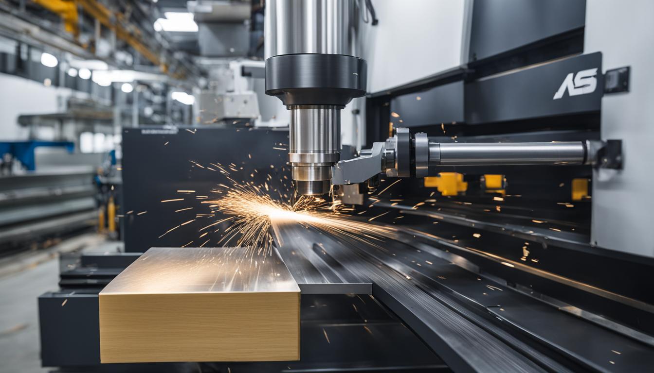
Computer Numerical Control (CNC) milling is a subtractive manufacturing process that utilizes rotating multi-point cutting tools to remove material from a workpiece, creating a desired part geometry. This highly automated method relies on precise digital instructions to achieve complex shapes and tight tolerances, forming the backbone of modern manufacturing across diverse industries.
The entire CNC milling workflow transforms a digital design into a physical component, demanding meticulous attention at each stage. From initial design to final inspection, every step is critical for producing high-quality, accurate parts. Understanding these stages is essential for any tooling engineer or machinist.
CAD Model Preparation for CNC Milling
The CNC milling process begins with a detailed 3D model created in Computer-Aided Design (CAD) software. This digital blueprint defines the part’s dimensions, features, and critical tolerances. Engineers must adhere to Design for Manufacturing (DfM) principles during this phase to ensure the part can be efficiently and accurately machined.
Exporting the CAD model requires careful selection of file formats to ensure compatibility with Computer-Aided Manufacturing (CAM) software. STEP (.stp or .step) is widely considered the best format for 3D CNC machining, as it preserves full solid geometry and transfers across different CAD/CAM systems without data loss. IGES (.igs) is a suitable alternative, particularly for surface and wireframe models.
Native CAD files, such as SolidWorks (.sldprt) or Autodesk Inventor (.ipt), can also be used, but neutral formats like STEP are generally preferred by machine shops to avoid software compatibility issues. It is crucial to verify units and scale during export to prevent critical scaling errors. Additionally, a 2D technical drawing should accompany the 3D model to specify tolerances, surface finishes, and other manufacturing notes not fully captured in the 3D data.
CAM Toolpath Generation and Post-Processing
| Parameter | Typical Value (Metals) | Typical Value (Plastics) | Notes |
|---|---|---|---|
| Standard Tolerance | ±0.005 in (0.13 mm) | ±0.01 in (0.25 mm) | Default for most CNC shops. |
| Precision Tolerance | ±0.002 in (0.051 mm) | ±0.002 in (0.051 mm) | Requires additional passes and frequent checks. |
| Surface Finish (Ra) | 125 Ra | 125 Ra | Achieved with appropriate finishing passes. |
| Aluminum RPM (Roughing) | 8,000 – 12,000 RPM | N/A | Using 2-flute aluminum-specific end mills. |
| Aluminum Feed Rate (Roughing) | 40 – 80 IPM | N/A | Adjust based on chip load and sound. |
| Steel RPM (General) | 1,000 – 3,000 RPM | N/A | Varies significantly by steel type and tool. |
| Steel Feed Rate (General) | 5 – 20 IPM | N/A | Requires careful chip evacuation and coolant. |
Once the CAD model is finalized and exported, it is imported into CAM software. This software acts as the bridge between the design and the CNC machine, translating the 3D model into precise machining instructions. CAM programmers define toolpaths, select cutting tools, and establish machining parameters like feeds and speeds.
CAM software generates toolpaths that dictate how the cutting tool will move to remove material, considering factors such as material type, tool geometry, and desired surface finish. It allows for simulation and validation of operations, helping to identify potential collisions and verify cut quality before any material is removed. This reduces material waste and ensures accuracy.
The final critical step in CAM is post-processing. A CNC post-processor is a software component that converts the generic toolpath instructions from the CAM software into machine-specific G-code. This G-code is the fundamental language that tells the CNC machine exactly where to move, how fast, when to change tools, and other operational commands.
Each CNC machine and controller combination requires a tailored post-processor to ensure compatibility and efficiency. The post-processor defines the exact syntax, cycles, tool calls, and coordinate transformations needed by the target CNC control. Without the correct post-processor, a perfectly simulated toolpath may not run correctly on the machine, leading to errors or poor results.
Machine Zero Setup (Work Coordinate System)
Establishing the Work Coordinate System (WCS) is a fundamental step in preparing the CNC machine for operation. The WCS defines the part’s zero origin relative to the machine’s own coordinate system, allowing the CNC program to describe component features from a practical part zero.
Machinists typically use G-codes like G54, G55, and others to store and select different work origins. These offsets tell the CNC control where the programmed part zero is located on the machine table. The WCS origin point is usually set at a known location on the fixture or workpiece, minimizing long tool approach moves.
Setting a work offset involves seating the component against locators and clamps, then measuring the datum using an edge finder, indicator, or probe. The measured relationship is then stored in the appropriate G-code offset. Verification of the stored value and a dry run of the first movement are crucial to confirm safe operation before running the complete machining cycle.
Automated Spindle Cutter Engagement
Automated spindle cutter engagement involves precise tool measurement and management, significantly enhancing machining accuracy and efficiency. CNC probing systems are integral to this process, measuring tool length, diameter, and detecting breakage directly on the machine.
Tool setting probes, often mounted in the machine spindle or a dedicated station, automatically measure tool length and diameter. This data is then stored in the machine’s tool offset table, compensating for variations and wear. This automation reduces manual setup time and minimizes human error.
Beyond initial setup, these systems can monitor tool wear and detect breakage during machining. If a tool breaks or wears beyond acceptable limits, the system can automatically stop the machine, preventing damage to the workpiece or machine. This capability is particularly valuable in unattended manufacturing cells and for maintaining consistent quality in mass production.
Part Dimension Inspection
Quality control is integrated throughout the CNC milling process, not just at the end. On-machine inspection, also known as on-machine measurement (OMM), utilizes a probe mounted in the machine spindle to measure part dimensions, features, and tolerances directly on the CNC machine.
This pre-machining and in-process probing can locate the workpiece, confirm its orientation, and set or correct the WCS, reducing manual setup time from minutes to seconds. After machining, the probe can verify critical features while the part is still fixtured, allowing for immediate adjustments if dimensions are out of specification.
For final, highly accurate dimensional verification, Coordinate Measuring Machines (CMMs) are indispensable. A CMM uses a tactile or non-contact sensor to record points on the component, comparing the geometry against nominal dimensions and Geometric Dimensioning and Tolerancing (GD&T) requirements. CMMs are crucial for verifying tight tolerances and complex geometries that manual tools cannot reliably check.
The integration of on-machine probing and CMM inspection ensures that parts meet exceptionally tight tolerances, which are critical in industries like aerospace, medical, and automotive. Standard CNC milling tolerances typically range from ±0.005 inches (0.13 mm) for general work to ±0.002 inches (0.051 mm) for precision applications, with some processes achieving ±0.0005 inches (0.0127 mm) on features like reamed holes.