
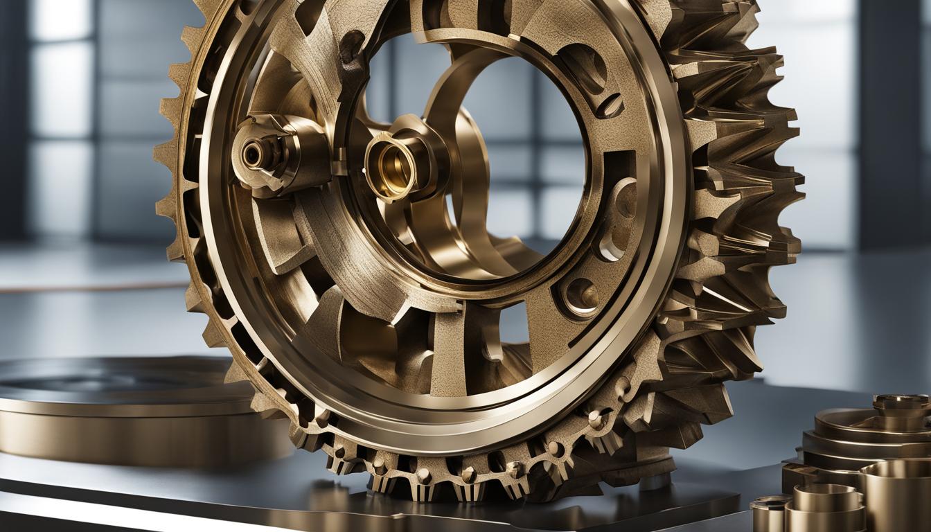
Three-dimensional Computer Numerical Control (CNC) machining represents a significant advancement in subtractive manufacturing, enabling the creation of intricate components from various materials. This technology leverages computer-aided design (CAD) files to precisely cut, mill, or turn raw stock into highly accurate parts. Modern 3D CNC machining offers unparalleled precision and design flexibility, producing complex geometries previously considered impossible.
The core principle involves automated toolpaths guided by digital models, ensuring consistent quality and repeatability across production runs. Industries from aerospace to medical and automotive sectors rely on 3D CNC machining for rapid prototyping and high-volume manufacturing of critical components. This method excels when dimensional accuracy, surface quality, and material integrity are paramount.
Understanding 3-Axis to 5-Axis Simultaneous Milling
CNC machining capabilities are fundamentally defined by the number of axes a machine can control. A 3-axis CNC machine operates along the linear X, Y, and Z axes, moving the cutting tool horizontally, vertically, and in depth. This configuration is well-suited for parts with flat surfaces or 2D geometries, such as simple enclosures or brackets, where all machining can be performed on a single plane.
However, machining complex parts with undercuts, angled features, or intricate three-dimensional contours often necessitates multiple setups on a 3-axis machine. Each repositioning introduces potential accuracy variations and extends overall cycle times. This limitation makes 3-axis systems less efficient for highly complex designs.
Five-axis CNC machining introduces two additional rotary axes, typically labeled A, B, or C, which allow the tool or workpiece to tilt and rotate simultaneously during the cutting process. This expanded range of motion enables the cutting tool to approach the workpiece from virtually any angle, maintaining optimal tool engagement and a constant chip load.
Simultaneous 5-axis machining coordinates movement across all five axes while cutting, allowing for continuous machining of complex shapes like turbine blades or orthopedic implants in a single setup. This significantly reduces the need for manual repositioning, minimizing cumulative errors and improving overall precision and surface finish.
Crafting Complex Organic Surfaces
| Feature | 3-Axis CNC Machining | 5-Axis CNC Machining |
|---|---|---|
| Axes of Motion | X, Y, Z (linear) | X, Y, Z (linear) + 2 rotational (A/B/C) |
| Part Complexity | Simple, flat, 2D/2.5D geometries | Complex, organic, multi-sided, undercuts |
| Number of Setups | Multiple setups often required for complex parts | Single setup for most complex parts |
| Precision & Accuracy | Good for simpler parts; cumulative error with multiple setups | Enhanced precision, tighter tolerances, reduced cumulative error |
| Surface Finish | May show ‘scallop’ marks on 3D contours | Improved, smoother finishes due to optimal tool angle |
| Cost per Part | Generally lower for simple parts | Can be lower for complex parts due to reduced cycle time and setups |
Machining complex organic surfaces, common in aerospace, medical, and automotive industries, demands advanced CNC capabilities. These surfaces often feature freeform curves, deep pockets, and intricate contours that require continuous tool engagement from varying angles. Achieving the desired geometry and surface finish is critical for functional performance and aesthetic appeal.
The ability of 5-axis machines to tilt the tool or the part into the cut allows for seamless machining of these challenging geometries. This eliminates the need for indexing or manual flips, which consume time and introduce risks of error. Surfaces that once required secondary operations can now be completed in a single cycle.
Surface finish is a crucial aspect of organic surface carving, directly impacting friction, wear resistance, sealing ability, and fatigue strength. Parameters like Ra (roughness average) quantify the microscopic texture, with lower Ra values indicating smoother surfaces. Typical values range from Ra 3.2 µm for general machining to Ra 0.8 µm or finer for precision surfaces.
Achieving superior surface finishes on complex organic shapes involves careful selection of tool geometry, cutting speed, feed rate, and lubrication. Modern practices emphasize maintaining optimal tool orientation and cutting engagement to reduce deflection, vibration, and heat, stabilizing the process and minimizing visual flaws.
Optimizing Ball Nose 3D Toolpaths
Ball nose end mills are indispensable for 3D contouring and finishing complex surfaces, particularly those with organic shapes. Their spherical tip allows for smooth, continuous contact with curved geometries, reducing the ‘stair-step’ effect often seen with flat-bottomed tools. This results in excellent surface finishes and significantly reduces post-machining polishing time.
Effective ball nose toolpath strategies are crucial for maximizing efficiency and surface quality. Constant scallop toolpaths are often preferred over parallel finishing, as they ensure uniform surface quality by maintaining a consistent cusp height across the entire machined area. This prevents inconsistent step-over marks.
Optimized feeds and speeds are paramount when using ball nose end mills for 3D contouring. For aluminum, recommended parameters for a Ø6 mm carbide ball nose end mill might include 22,000 RPM, a feed rate of 1,200–1,800 mm/min, a step-over of 8–12%, and a step-down of 0.05–0.10 mm. For steel, these values would be adjusted to around 10,000 RPM, 450–650 mm/min feed, 6–8% step-over, and 0.03–0.06 mm step-down.
Proper toolholder selection, such as ER32 or SK16, and tool geometry, like 2-flute for aluminum or 3-4 flute for steel, also play a significant role in optimizing performance. High-speed machining (HSM) strategies, which prioritize constant tool engagement and chip load, further minimize chatter and reduce machining time.
The Foundation of CAD 3D Surface Modeling
Accurate 3D surface modeling in CAD (Computer-Aided Design) software forms the indispensable foundation for successful 3D CNC machining. These digital models precisely define the dimensions, angles, and tolerances of a part, providing the critical data for subsequent CAM (Computer-Aided Manufacturing) programming.
Advanced CAD platforms like CATIA, Siemens NX, and Creo are renowned for their robust surface modeling capabilities, particularly for complex organic shapes and Class-A surfacing requirements in aerospace and automotive industries. SolidWorks and Autodesk Fusion 360 also offer powerful solid and surfacing tools suitable for a wide range of engineering applications.
Key elements of effective CAD design for 3D machining include ensuring all dimensions and tolerances are within specifications, detailing features like chamfers and hole positions, and considering manufacturability early in the design stage. This proactive approach helps avoid machining problems caused by overly complex structures.
The transition from CAD to CNC involves converting these 3D models into machining code using CAM software. This process demands data integrity and accuracy to prevent machining errors, with CAM systems offering various multi-axis cutting strategies to fully utilize the flexibility of advanced CNC machines.
Leveraging Multi-Directional Cutting
Multi-directional cutting, a hallmark of 5-axis CNC machining, significantly enhances manufacturing efficiency and part quality. This capability allows the cutting tool to approach the workpiece from numerous angles, enabling the machining of complex features and undercuts that would be inaccessible with traditional 3-axis methods.
The primary advantage of multi-directional cutting is the reduction in the number of setups required. By machining multiple sides of a part in a single operation, manufacturers eliminate the time and potential errors associated with repositioning the workpiece. This streamlines production, shortens cycle times, and lowers overall project costs.
Furthermore, multi-directional cutting allows for the use of shorter, more rigid cutting tools. When the spindle can tilt into tighter areas, less tool stick-out is required, which reduces chatter, minimizes tool deflection, and improves surface finish. This also extends tool life and protects spindle bearings from unnecessary side loading.
This advanced cutting strategy is particularly beneficial for industries requiring tight tolerances and superior surface finishes, such as medical device manufacturing and aerospace component production. The ability to maintain optimal tool orientation throughout the cut ensures consistent material removal and exceptional part quality.