
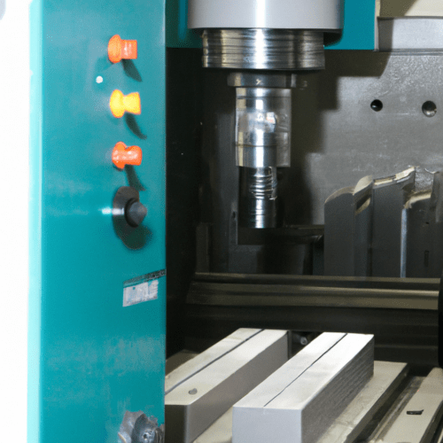
A milling machine is an industrial machine tool that precisely removes material from a stationary workpiece using rotating multi-point cutting tools. This subtractive manufacturing process is fundamental across various industries, producing flat surfaces, slots, contours, and complex three-dimensional geometries with high accuracy. Modern milling machines, especially Computer Numerical Control (CNC) variants, are indispensable for achieving tight tolerances and repeatable results in manufacturing.
Unlike a lathe where the workpiece rotates against a stationary tool, a milling machine’s cutting tool rotates while the workpiece remains fixed on a table. The machine’s table then moves along different axes, guiding the material into the cutter. This controlled interaction allows for the systematic removal of material, layer by layer, in the form of chips, to achieve the desired final shape.
Fundamental Milling Operations: Face and End Milling
Face milling is a primary operation used to create flat, smooth surfaces on a workpiece by removing material from its top face. The cutting tool, typically a face mill or shell mill, features multiple cutting edges on its face and rotates perpendicular to the workpiece surface. This method is highly efficient for machining large, flat areas and achieving superior surface finishes, often as fine as 0.8 Ra micrometers.
Modern face milling techniques often employ carbide or ceramic inserts, which enhance cutting action and extend tool life. The selection of cutter, number of teeth, feed rate, cutting speed, and depth of cut are critical parameters influencing finish quality and precision. For roughing operations, the objective is rapid material removal, while finishing focuses on achieving the desired surface smoothness.
End milling, conversely, utilizes cutting tools with cutting edges on both their periphery and face, making them versatile for slotting, pocketing, and shaping complex contours. End mills are crucial for detailed, three-dimensional shapes and profiles, allowing for multi-directional machining tasks. The number of flutes on an end mill, typically ranging from two to six, directly impacts chip evacuation and the size of the chip pocket.
Optimizing end mill cutting parameters involves balancing spindle speed (RPM), cutting speed (VC), and feed rate (IPM) to achieve optimal performance and tool life. Factors such as workpiece material, tool geometry, machine rigidity, and the specific operation type (roughing vs. finishing) significantly influence these settings. For instance, softer materials like aluminum allow for more aggressive feeds and higher RPMs, while harder materials like stainless steel require reduced speeds to prevent overheating and tool wear.
Specialized Milling Techniques: Slotting and Profiling
| Material | Cutting Speed (SFM) | Chip Load (inch/tooth) | Recommended Flutes |
|---|---|---|---|
| Aluminum 6061 | 800 – 1,000 | 0.003 – 0.005 | 2-3 |
| Steel 1018 | 300 – 400 | 0.002 – 0.003 | 3-4 |
| Stainless 304 | 150 – 250 | 0.001 – 0.003 | 4-flute (AlTiN/TiAlN coated) |
| Titanium Ti-6Al-4V | 60 – 100 | 0.001 – 0.002 | 4-flute (AlTiN/TiAlN coated) |
Slot milling, also known as slot cutting or groove milling, involves using a milling cutter, usually an end mill, to remove material along a straight or curved line, forming an elongated cavity. This operation is critical for creating features such as keyways, T-slots, and precise channels for components like rails, sliders, or fasteners. Slotting is considered one of the more aggressive milling operations because the cutter is often fully engaged on both sidewalls.
The process typically involves several stages: workpiece setup, an entry strategy (like ramping or helical penetration to reduce impact), roughing to remove bulk material, and a finishing pass to refine the slot’s width and sidewall quality. CNC programs define the slot’s dimensions and position with exceptional accuracy, ensuring proper assembly fit. Modern CAM software can generate advanced toolpaths, such as trochoidal milling, to improve chip evacuation and reduce heat, boosting productivity by 25-40%.
Profiling is a CNC machining process that cuts along the outline of a part or feature, creating complex external or internal contours. This technique is essential for shaping boundaries, improving edge accuracy, and finishing part geometry in 2D or 2.5D machining. It is widely applied in industries like aerospace, automotive, and mold-making for components requiring intricate designs and smooth finishes.
Profiling operations are often divided into roughing, semi-finishing, finishing, and super-finishing stages, each tailored to specific material removal rates, surface quality, and dimensional tolerances. The process demands strong control over tool deflection, cutting forces, and workpiece stability, as small deviations can significantly impact dimensional accuracy and surface quality, particularly on thin walls or long contour paths.
Integrated Machining: Drilling and Tapping
CNC drilling is a computer-controlled subtractive machining process dedicated to creating precise round holes in various materials. A rotating drill bit is forced into a stationary workpiece, with the G-code specifying coordinates, feed rates, spindle speeds, and depth. This automation ensures high precision, consistently drilling holes with tolerances as tight as ±0.005 inches (±0.127 mm).
Optimizing drilling operations requires careful consideration of feed rate and spindle speed, which are functions of material hardness, tool diameter, and hole depth. Spot drilling often serves as an initial step, creating a guide for subsequent drilling and ensuring accuracy for deeper holes. Proper workholding and drill bit geometry are crucial for chip evacuation and preventing deflection, especially in hard metals or thin sections.
Tapping is the process of cutting internal threads into a pre-drilled hole, allowing parts to accept screws and bolts for firm fastening. In CNC rigid tapping, the spindle speed and axial feed rate must be precisely synchronized with the thread pitch. This synchronization is critical; a feed rate mismatch can cause the tap to rub, overload, or lose synchronization, leading to broken taps or damaged threads.
Key tapping parameters include spindle speed, feed rate, pre-drilled hole size, coolant application, and tap geometry. Machinists often aim for a pre-drilled hole size that yields 60-75% thread engagement to reduce tapping torque and extend tool life. For example, an M10 x 1.5 thread typically uses an 8.5 mm drill.
Understanding Machine Axis Movement
Milling machines operate within a coordinate system, typically defined by X, Y, and Z axes for linear movement. The X-axis represents longitudinal movement (left-right), the Y-axis denotes transverse movement (front-back), and the Z-axis controls vertical movement (up-down). These three orthogonal directions are fundamental for machining in three-dimensional space.
Advanced CNC milling machines, such as 4-axis and 5-axis systems, incorporate additional rotational axes to enhance machining capabilities. A 4-axis machine adds a rotational axis, often designated as ‘A’ (rotation around X), ‘B’ (rotation around Y), or ‘C’ (rotation around Z), allowing the workpiece or tool to be rotated. This enables machining on multiple sides of a part without re-clamping.
Five-axis CNC milling machines further expand this capability by adding two rotational axes, allowing the tool to approach the part from virtually any direction. This significantly reduces the need for multiple setups, improves positional accuracy between features, and is invaluable for complex surfaces, deep cavities, and intricate geometries common in aerospace and medical device manufacturing.
Machine movements are controlled by G-code, a programming language that instructs the CNC machine on where to move, how fast to move, and what path to follow. Commands like G00 (rapid positioning) move the machine at maximum travel speed without cutting, while G01 (linear interpolation) commands a straight-line cut at a specified feed rate. G02 and G03 commands are used for circular interpolation, defining clockwise and counter-clockwise arcs, respectively.